Showing posts with label Sharp Stewart. Show all posts

Sunday, 7 February 2021

0-16.5 Engines

Updated 2022


© 2020 David Hurst All Rights Reserved

It was at the Halifax 2019 model railway show that I was tempted by an old Hornby “Smoky Joe” style 0-4-0 engine sitting in one of the second-hand boxes. I had seen some ideas on YouTube about add simple cylinders and coupling rods to these which looked convincing when completed. Little did I think it would lead me into an interest in a new scale of 7mm.

It was some weeks later when I came round to see what I could do with the old Hornby chassis, my first thoughts were the type of engine I could build from the existing bodywork. I found a very good source of inspiration at the Smallbrook Studios web site. They do resin body conversions for the 00 chassis in a 7mm scale, there is also a good catalog of rolling stock and detailed parts.

I found one saddle tank conversion from a Hornby “Thomas The Tank Engine” Bill Loco just what I liked. I look on eBay and was lucky enough to find a body for the Bachmman version of the Bill engine. My plan was to scratch build a new cab and smokebox door, then buy a cast resin dome and water tank lid. Other details I could get from various other sources.

My next thoughts were on the cylinder conversion, I looked up the You Tube video I had seen previously. The parts used on that were spares form a Hornby Class 28XX 2-8-0 Loco Valve gear, I got a set of these from Peters Spares. Only the crossheads and slide bars would be needed for this job so the other bits would be saved for something in the future. To attach the crossheads and the coupling rods I required some very small 14BA machine screws nuts and washers, and eBay came up with a suitable supplier of these.

I would need to build some simple cylinders to fit onto the existing chassis, and remove the existing moulded ones. To do this I laminated together a couple of Placticard blocks and a bridge between them to form a cylinder arrangement. Holes were drilled to give a clearance fit to the crossheads and a tight fit for the slid bars. The chassis was cut to allow the cylinders to sit in the correct place.

The next job was to alter the coupling rods, these needed to be cut in front of the dummy cross heads, and a clearance hole made in the centre of the rod for the 14BA screws. Once done the screws can be passed through from the back of the coupling rods, a washer placed between them and the crosshead, then a couple of nuts used on the outside of the crossheads will lock them in place. It all needs to be a loose fit to work. Once all is fitted together a quick test run will let you know if any adjustments are required for smooth running.

Once the chassis was running, I started thinking, could I 3D print a version of the cylinders and crossheads. So off I went to the computer and came up with a version that used 0.7mm brass wire for the slide rods and cylinder rod. I used White Versatile Plastic to create the prototype print and after a couple of attempts, I got them working. So I added these to the loco I was building.

© 2020 David Hurst All Rights Reserved


There came a point when I had to add the Bachmman body to the Hornby chassis, This was not a straight forward fit, but with a little cutting and a bit of Milliput Putty, it went together. By removing some plastic from the bottom of the footplate around the front and rear couplings and infilling a small section to the front of the footplate, where an 8 BA nut could be bonded to the underside. The chassis in turn needed a slot cutting at the back to allow it to fit the rear bodywork. A hole was drilled through the front of the chassis in the centre of the cylinder bridge to allow an 8 BA screw to pass through, this is to hold the chassis and body together. NEM Coupling pockets were fitted in place encased in Milliput putty at both ends of the chassis,

Once I had completed the scratch-built body the natural progression was to see if I could produce a 3D printed version of a body. The only thing to decide what engine to have a go with. In the end, I worked on two types the Skylark style and Peckett style engines which I had already done in 009. These were scaled up and reworked around the new chassis. The idea being, to create a body shell with the cylinders already attached. These could be used as simple conversion to the Hornby chassis by removing the cylinders and couplings from the Hornby chassis, then the chassis would simply push into place under the new body.

© 2020 David Hurst All Rights Reserved


If you wanted to go further you removed the cylinders from the printed body also and add the additional printed cylinder block and crossheads to the chassis to create a more detailed version of the engine. They would also have pockets in the buffer beams to accommodate NEM coupling pockets at the correct height. Well, it all seemed like a good idea.

© 2020 David Hurst All Rights Reserved

I had two prototype prints done in White Versatile Plastic to try these out, they both fitted the chassis as expected and work well as simple conversions.

I have also done a third body now, this one is a quarry Hunslet style with a cap that can be built in three versions, one open, one with no back, and a fully enclosed version. I just could not make my mind up which I liked best.


I Have now added a Sharp Stewart Tattoo Saddel tank to the ranks of the 0 gauge fleet of small engines. It is printed with some alternative parts such as funnels. This one is designed to run on the 0-6-0 Electrotren chassis with the rear wheels swaped for a 10mm solid disk type to form a pony wheel.  


© 2022 Tom Waddell All Rights Reserved

© 2022 David Hurst All Rights Reserved


 I have added a list of additional fitting that I used and the supplier below. The three printed bodies and cylinders conversion are available on Shapeways at:

https://www.shapeways.com/shops/model-engine-works?section=0-


16.5+Engines&s=0


List of Parts:

Hornby 0-4-0 Chassis or Electrotren 0-6-0 Chassis

Printed or scratch-built chassis blocks

Brass 0.7mm brass wires

Parts from Peters Spares

Hornby X8834W Class 28XX 2-8-0 Loco Valve Gear Set Weathered.

Couplings and NEM pockets

sales@petersspares.com

8BA Screws nuts and washers

14 BA screws nuts and washers

© 2020 David Hurst All Rights Reserved


Sunday, 5 February 2017

00n3 Clogher Valley Sharp Stewart Engine

Updated March 2020

©  2017   Paul Titmuss   All  Rights Reserved
This has been a very interesting project for me as it was my first collaborative modelling project. I would like to thank Paul Titmuss for his trust in me to come up with the goods and all his help in getting the model to the level of detail we have achieved. It got off the ground in September 2016 at the Halifax Model railway exhibition where Paul and I had arranged to discuss an idea that he had been trying to get help with for some time.

The idea was to have a simple and interesting steam tram engine as an introduction to 00n3 gauge accessible to all skill levels. Like 009 gauge has the Kato tram chassis and a choice of 3D printed bodies for tram engines to get you started. This is what Paul is hoping to achieve with this model and some others that CWRailways produce for 00n3. 

Whilst briefing me on the engine, Paul mentioned that he would be showing his Annascaul layout at The Ulster Folk and Transport Museum in November 2016 and suggested it would be good to show the engine off on its home ground. So no pressure there then, with just over six weeks to draw up, get it printed, and to allow time for Paul to finish the model, this was good motivation to get my skates on.   

©  2017   David Hurst     All  Rights Reserved
I had already done a 009 3D printed version of the “Clogher Valley” tram engine, so I was familiar with the subject, but this was to be a true to 4mm scale version with much more detail than my original prints had. Our original thoughts were that I could alter the drawing file for the larger tram engine No2. As this was already drawn up to work with a Halling Chassis, it seemed an easy solution. But it is sometimes much easier to start again than pull something apart and try and to remodel it, especially a C.A.D drawing. So working from photos and some line drawings I started building a new 3D model from scratch. We had the print done by mid-October and Paul did a great job to get it ready for the exhibition in works grey with a few modifications, which we added to the final drawings. 

©  2017   Paul Titmuss   All  Rights Reserved

Build Preparation
Priming and smoothing is necessary on both Strong White Flexible-Polished and Frosted Ultra Detail plastics. We will take F.U.D. first as there is a cleaning process to get the surface ready for priming. Some of the support waxy residue will still be present and it is necessary to remove this. First the print should be dipped in white spirits for a short time to loosen and soften the wax, after this transfer it to some warm (not hot) soapy water to wash the softened wax away. A small stiff paint brush may help here to access the nooks and crannies on the print, then leave to dry thoroughly before painting.

There are two approaches to building the model and both give good results as Paul and I show. The first is to fully assemble the model adding most of the details except glazing and cab interior, then prime and smooth ready for final painting (all paintwork was done by hand on Paul’s model). The other method is to prime and smooth the individual parts. In my case I worked with the footplate, the main body, the cab roof, and the oil lamp. They were all lightly spray-primed in white (to show up the later wire-work clearly). Then I added most of the detailed items such as wire for pipes and handrails, smokebox door handles, valve gear, and whistle. These individual parts were all lightly spray-primed on the model. 

©  2017   David Hurst     All  Rights Reserved

Adding Ballast
As with all 3D prints it is advisable to add weight to the print. On this engine, the tram skirts provide an ideal location, as the weight is low and it keeps the model from being top heavy.

Fitting the Motor Bogie
First you will need to remove the couplings which are printed on the underside of the footplate.


©  2017   David Hurst     All  Rights Reserved

The Halling Motor Bogie is intended to ease into the foot plate section of the print straight from underneath, the saddle sits over the magnet on top of the motor giving a snug fit side to side and sets the motor level with the footplate. The lower brackets / tabs under the footplate are intended to be a little tight, on the FUD print it may be prudent to sand a little off the inner face of the brackets, to obtain a fit that will just hold the bogie without it falling out, the brackets on the FUD print have been reinforced to allow for the brittle nature of the plastic.

©  2017   David Hurst     All  Rights Reserved

The footplate has also got a couple of scoops taken out of the top surface, this is to allow for the tendency of the motor shaft to move back and forward slightly in operation. 

©  2017   David Hurst     All  Rights Reserved

Adding the Wire-Work
Handrails and pipes were the next items to be fitted to the main body of the model. The prints have been done with a set of small pilot holes to help in positioning of the various handrails, pipes, valve gear, whistle and lamps. There are more than is needed but these are easily filled if not required. It will be necessary to drill out to size these holes particularly on the SWF-P prints. As a guide, the wire used for the handrails was .045 mm brass, the pipes from the smoke chests on the footplate were the same 0.45 mm brass. The pipe running from the smokebox to the cab was 1 mm copper on my version and .75 mm brass on Paul’s.

©  2017   David Hurst     All  Rights Reserved

Adding the Valve Gear
The valve gear rods which fit into the steam chests at the front of the footplate, are handed with the front-end fitting into the steam chest first, then they are lowered into the two holes in the upper face of the foot plate.

©  2017   David Hurst     All  Rights Reserved

Smoke Box Door Handles
We used two types of handles for the smokebox door. Paul used the brass turning from Markits; I on the other hand, used a set of etched wheels from RT Models some of which were also used in the cab, and a white metal smokebox door Dart/handle. Both achieve the same result but mine was somewhat fiddly to fit.

©  2017   David Hurst     All  Rights Reserved

Couplings
There are a set of basic couplings printed within the footplate section for the model which will need to be cut out before the motor bogie can be fitted in place. The pockets on the front and back buffer beams will take Peco NEM pockets or the couplings supplied. I have made the shafts on the printed couplings a little smaller in height than the pockets to allow the builder to pack them at the top or bottom for lining up with existing stock if required.

©  2017   Paul Titmuss   All  Rights Reserved

Building the Cab Interior
A crew and the cab interior were the next job to look at. I have not been able to find any pictures for the cab interior of these engines, so it is a blank canvas. Both Paul and I have had a go at what we think it may have looked like, you may have your own ideas. I used Dapol trackside work crew figures, sheet plasticard, some wheels off the brass etch used for the smokebox door, and odd bits of old left over kits. 

©  2017   David Hurst     All  Rights Reserved

Additional notes on Cab Interior Layout
Paul has found some further information on the interior that indicates a different layout on the left-hand side facing the boiler, this make since that there is no coal bunker internally just a hatch to access the external coal bunker, and the break column and handle are over at the side in the middle of the cab. This may have been the layout once the additional space was added to carry coal above the firebox and boiler. 


©  2017   David Hurst     All  Rights Reserved

Adding the Glazing
The larger windows were eventually glazed on the engines to help protect the crew from the weather with bars on the inside to protect the glass. I do not know if glass was also added to the windows next to the bunker. As I have printed the model with the bars already in the windows, I cheated and added glazing on the inside of the bars. Paul decided to leave the glazing out altogether, which gives a better view of your work on the inside of the cab.


©  2017   David Hurst     All  Rights Reserve

Painting
The painting was tackled in two ways: Paul’s model was all hand painted in matt Humprol paints to be finished with a coat of satin varnish and lightly weathered; my version was sprayed in separate parts using Humbrol acrylic satin Brunswick green paint for the body and cab roof. The footplate was done in a matt acrylic spray paint. Then the details such as the cowcatcher, valves, window bars were picked out by hand. The cab interior figures were all hand painted. 


Adding Coal
The Coal is the real the thing crushed, and held in place with PVA glue. 


©  2017   David Hurst     All  Rights Reserved

Transfers
My reason for using satin finish paint is to allow for the waterslide transfers to be applied with ease. I had a sheet of Cheltenham Medium, 2mm / 1mm general gold lettering and numbers from Fox Transfers which were used on some of my previous Clogher Valley engines. The names on these engines were laid out on an ark so I have used a small paper template to assist in lining the lettering upon the ark and getting the spacings between the letters right. The Clogher Valley monogram of interlaced letters was created by over laying a C, R and V closely. Generally “CV” only was used, but on Blackwater “CVR” was also used. I did the full CVR to see how it worked. Once the transfers have dried I fix them with a coat of oil based Humbrol satin varnish and apply this as part of the finishing coat over the entire paintwork on the engine.    


©  2017   David Hurst     All  Rights Reserved

Weathering
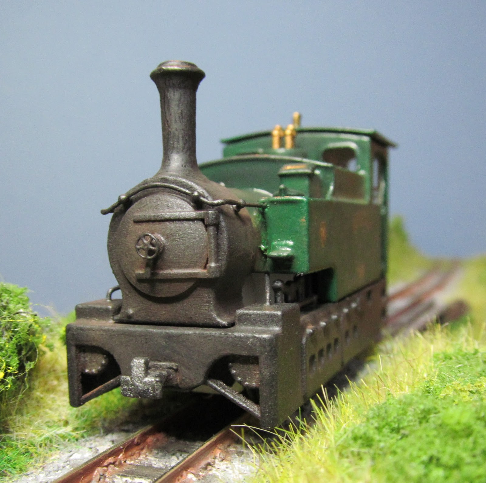
This is a method of applying weathering soot and dirt with oil pastels. I have tried this method on a few models and it does give reasonable results. Using colours such as black, burnt umber, light red, cadmium orange and sienna oil pastels, I use a craft knife to slice these and create a powder. This is saved in a small divided container. I have a soft No 6 size paint brush and dab this into the power and then rub the brush onto the surface of the model as required. The results gives a scuttle soot, rust and general dirt finish.    


©  2017   Paul Titmuss   All  Rights Reserved
©  2017   David Hurst     All  Rights Reserved

October 2017 launch on Shapeways of the new FUD print including detailed parts:
I am pleased to announce the launch of my revised Frosted Ultra Detailed Clogher Valley Tram Engine. Having work on adding additional details to the print and also incorporating the detailed parts print within the main body of the model, this has both enhanced the model and reduced the cost. See this latest model at the Model Engine Works on Shapeways.


If you would like a copy of this model visit Model Engine Works at: https://www.shapeways.com/shops/model-engine-works


©  2017   David Hurst     All  Rights Reserved

©  2017   David Hurst     All  Rights Reserved


©  2017   David Hurst     All  Rights Reserved

Please note:
There are two prints produced to complete the models shown in this article; these are the main body which is available in Strong White Flexible Polished or Frosted Ultra Detail. Also, a set of detailed parts in Frosted Ultra Detail, this is to give the Strong White Flexible Polished print a level of detail that would not be possible in that material alone.


©  2017   David Hurst     All  Rights Reserved

A new 009 version of the model has been added to Shapeways, this has been designed to run on the new Kato 11-110 chassis and is slightly reduced in size to work better on 9mm track. 

Sources of Additional Materials

Smokebox door handles from: 
Markits. Code M4SBDH4 ref GC/LNWR.  
RT Models ref 4AGB0MW etched wheels and 4AGB00D Smokebox door Dart/handle.

Hadrail and knobs:
Alan Gibson Brass Wire ref 0.45 mm G4M136 and handrail knobs 4mm short ref G4M53.

Couplings:
Couplings pockets Peco NEM pockets ref GR-103.
Greenwich Coupling ref CPL 3 for NEM pockets.

Engine crew:
Crew ideas Dapol C002 Railway Workmen. 
Modelu-3d printed railway figures.

Engine name and number:
Fox transfers also possible use for monogram.


Sunday, 11 October 2015

Sharp Stewart 0 4 2

Looking around there are many really good model tram engines but some just stand out from the crowd. Such is the case for me with the numerous models of the Clougher Valley railways original engines, the 0 4 2 Sharp Stuarts, captured so well by Paul Windle’s reduced size version.It took me a while to discover where the original of this engine came from, I eventually came across a picture of it on the Belfast Telegraph’s archives, pointing me to the Clougher Valley railway as its home. I now have a treasured copy of The Clougher Valley Railway by E.M.Patterson which is a brilliant source of information about this tramway / railway.


Having just completed a course to learn 3D Cad I was advised to practice on a subject I would enjoy, so what better subject than this engine. I decided to work on a compact version to fit a Kato 11-104 chassis, and this was the first thing I drew up since I could use this chassis drawing on other projects as well.


Cad file of 0 4 2 Sharp Stuart 


The whole process was an interesting challenge as I was planning to use 3D printing to produce the model, a process which meant a lot of reading to find out about the different material available.
My final choice of plastic was an acrylic which would provide me with fine detail; I had selected two suppliers to try, one being Shapeways and the other CWrailways   http://www.cwrailways.com . My first attempt was sent to Shapeways, which was a single piece body and had quite a few drawbacks. Access to get detail and crew into the cab was one, I should have made the roof separate. The other was that areas of the body shell were too thin, which showed up as the acrylic is very brittle and easily damaged. A corner of the roof overhang broke off, so I added a further layer of thin plastic card to the top surface. The funnel was elegant but far too thin, I ended up cutting it off and adding a Gem white metal one. Also the bottom edges of the tram skirts were thin and seemed pretty fragile, so again I did a bit of reinforcing with plasticard.
By the time I got round to ordering my second prototype I had completed the first one. I finished it in Brunswick green and named the engine Erne No 6 after one of the Clougher Valley railway originals. 


With modifications done to the drawing of the second prototype, I sent the STL file of to Chris at CWrailways who had kindly advised on some changes to the model. When this second model had been printed it was more robust and I was pleased with the results. There were a few little niggling issues that prompted a return to the drawing board, but these were tweaks not major things.
  

With the body shell form CWrailways there is no need to remove the support wax residue.  Unlike the Shapeways version, you can rub over the surface with a wood lolly stick or similar tool with rounded edges, and this helps to remove the layer effect evident on the model’s surface. A good two or three thin coats of spray primer will level the surface ready for the final brush or spray finish.   
Once the first coat of primer was added to the body and any blemishes to the surface corrected, I then added hand rails and other details. The hand rails I used were from Mainly Trains  http://www.mainlytrains.co.uk/ ; the make was Gibson, which uses 0.45mm brass wire and some really small brass handrail knobs, one of the short versions of these were used on this engine. They are fiddly to handle but look very much to scale.


I made the head lamps at this stage using 3 disks of 1 mm thick plasticard to form the body and two small squares fitted top and bottom to give the lamp its distinctive shape. These are the later acetylene lamps used on the C.V.R. The lenses were formed by using a suitable sized drill bit and forming a concave shape hollow in the face of the lamp, which was then lined with aluminium foil shiny side outward. The lamp was then painted matt black and left to fit to the cab between the windows after painting was completed.


It is necessary to cut down the Kato 11-104 chassis. The cuts are made at both ends just at the outside of the fixing screws holding the unit together, you will need to file a bit of the metal base back to this point also. A couple of little bits of lead strip were added at each end of the chassis just under the fixings.


The only other ballast I added to the second engine was two pieces down the inside of each skirt. The first engine had the lead fitted to the inside of each water tank and under the coal bunker. Both run well with the weight added.


I cut some clear plasticard for the cab windows which was much easier to fit with no roof on the cab and this was not glued in place until the paintwork was completed. A suitable figure was selected from the Dapol range of trackside workmen, adjusted to take up a relaxed stance in the cab and painted. This was then put aside to be added with the glazing when painting of the body was finished.

The final addition to the shell was Peco NEM coupler pockets. These are glued together which is easier when they are whole. A small strip of 0.5 mm plasticard was used to locate the pockets in the correct position so they did not stick out too much on the face of the body, (but this is personal choice). They were then cut down from the Z shape to form an L shape, this being necessary because of the limited space I have allowed for the chassis.


As mentioned earlier I added three thin coats of primer to this model, the finishing coats were applied by spray and brush. Starting with the red on the cowcatcher and the area around the front coupling, I have a red spray paint purchased from Aldi which gives a good bright red finish. The body and foot plate requires masking off well when using this, and I also use masking fluid in the areas around the cylinders and coupler pockets. 


Once a couple of coats of this was applied I moved on to the main bodywork, for which I used Revell SM331 which is similar to Crimson Lake. The black areas round the skirts, smoke box and cab roof were finished with Hunbrol Matt black 33.
The finishing touches round the windows and safety valves are in Hunbrol metallic bronze. It is usually a good bet to leave the model for a few days after painting the top coats, as particularly on the Shapeways body shells there always seems to be a slight reaction to the carrier wax residue, and the paint stays soft. When I am quite happy that the paint has cured I add the cab glazing and crew, then fix the roof in place.
The engine name and number are added next using Model master water slide transfers. An ark cut from masking tape is used as guide to get the individual letters of the name to form a curve. 


When these have dried overnight I apply a coat of matt varnish, usually Humbrol enamel brushed or acrylic spray.


The final touch is to add the coal. This is done using PVA wood glue and crushed real coal. The coal bunker is filled with the PVA and the coal pieces added using a small piece of tube sliced back at an angle to form a scoop. This gives me a bit of control where the coal is going.  


This model has opened up all sorts for possibilities for me, Ideas are there and I am hoping to draw up a few more and print them.

If you would like to obtain a copy of the 3D print it is available at.
https://www.shapeways.com/product/TYBBEH7A6/009-irish-tram-engine?li=shop-results&optionId=57962544&rc=SearchResults
http://www.cwrailways.com/009-ng.html

009 Tram engine 2

Having been ask to create a version of this little tram engine to suit a Hallings 12 mm chassis for HOm12 gauge, I found that the new larger engine also suited the Kato 11-103 chassis, and it is this version which I have made here see pictures below.


I have had a prototype printed in FUD, and would be confident that it should print in SWF as well, as its smaller twin dose. 


http://www.shapeways.com/product/KSK5TV4JJ/?key=f5755833c042d20fc32b50583926515c&optionId=60192392