Friday 16 November 2018

009 Tattoo Class 0 4 2

 A venture into white metal kit building.
©  2018   David Hurst     All  Rights Reserved

The Kerr Stuart “Tattoo Class” is a favourite of mine and I have built quite a few models based around this type of engine. They were built by Kerr Stuart & Co in large numbers at the beginning of the 1900’s as a small workhorse engine, the majority being for 2 ft gauge lines and having outside frames, to accommodate the firebox. There were however quite a few built for wider gauges 2ft 6” and 3ft with inside frames. Being a basic engine, most had open cabs, though some had enclosed cabs added in different forms at the time of manufacture, or later by their owners. 
©  2018   David Hurst     All  Rights Reserved

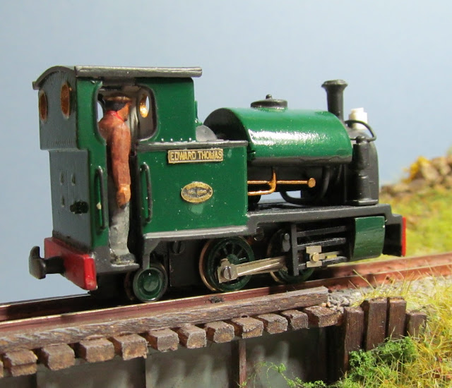
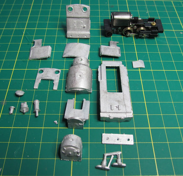
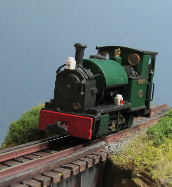
A Christmas gift I once received was a white metal version of the Talyllyn Railway’s engine Edward Thomas. I had also had an Ndrive Productions 0 4 0 Chassis which was a suitable size to fit the kit, needing only the addition of a rear pony wheel. The spark that prompted me to finally build the model was a holiday in mid Wales, where I planned to visit the Talyllyn Railway and perhaps see Edward Thomas in person. 
©  2018   David Hurst     All  Rights Reserved

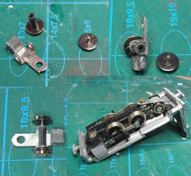
I started by looking for the right candidate for a pony wheel, which needed to be around 5.3 mm. There was also the question of how to mount the wheel onto the chassis. Now Ndrive Productions (Neville) has a nifty little etched universal mount to do this job, a cross with several holes to fit the wheels and create a pivot. The only thing was that you needed a wheel set that separates from the axles (to pass through the holes in the pony truck etch). 
 
                                                         ©  2018   David Hurst     All  Rights Reserved
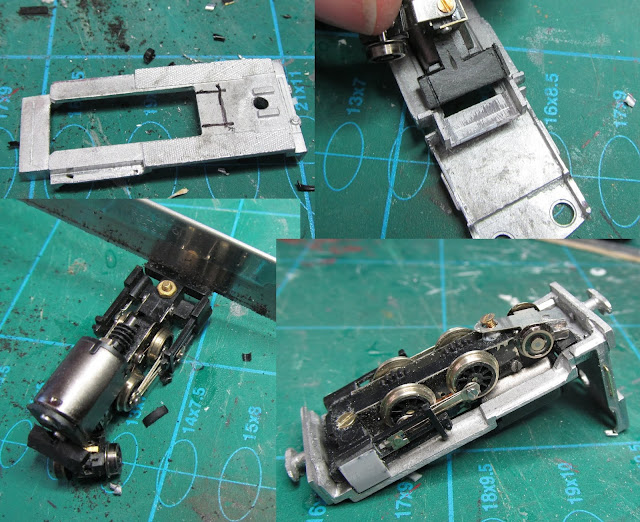
I discovered that the Kato wheel sets are held together with a plastic tube (to electrically insulate the wheels) and are close to the right size for the pony wheel. By filing off the pinpoint bearing and carefully opening out the hole in the etch I had a basic pony wheel and mount. Having selected the suitable pivot hole on the etch, it was then a fiddly job to drill a small very accurate hole to take a 10 BA cheese head machine screw in the base of the chassis. Care is needed as you are working very close to the gears, (so don’t slip)?

This pony wheel assembly is very light and does not ride on the track well in reverse, although its wheels are free moving and it pivots easily. The etch being a cross shaped form does give the opportunity to add a little weight at the back of the wheels. The 10 BA cheese head needed to be filed down to a thin disk with a new slot cut across it, to avoid catching on the track at points. It was also necessary to file down the wheel pick-ups at the back of the chassis or the etch for the pony wheel would not pass over these.
The other areas of the chassis that needed to be fettled were above and in front the cylinders. These needed to be filed off and cut to allow the chassis to sit tightly up to the underside of the footplate. Also, the width of the rear bar needed reducing at both sides.
©  2018   David Hurst     All  Rights Reserved

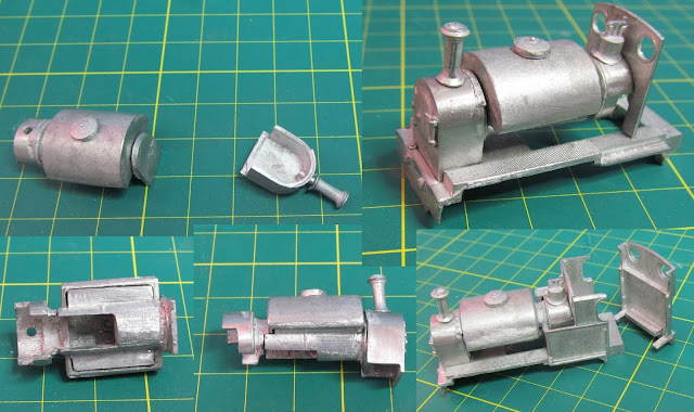
To say that this kit was designed for another type of chassis, it was a surprisingly good fit. There was a small area for the cab front and underside of the boiler to remove to accommodate the slightly bigger motor, a few tweaks to the footplate at the front a small square to cut out for the worm gear, and that was it. The body and the chassis were held together by forming a small L shaped bracket at the back and glueing this to the underside of the cab, this formed a channel for the rear of the chassis to hook into.
©  2018   David Hurst     All  Rights Reserved

The front fixing of the bodywork uses the existing counter-sunk machine screw and nut supplied with the chassis. This was done by slightly deepening the counter sink in the chassis and glueing the nut to the top face of the footplate situated above the existing hole. All of this was done before the bulk of the model was put together. I also added the blast under the saddle tank and in the smoke box before final assembly. It needed more weight at the front to counter the overhang of the cab, and partly to reduce this weight. I did not use the cab roof since this appeared too thick and bulky ,but instead formed one in Plasticard sheet, creating the gutters which the metal roof lacked.
Other modifications to the model included adding brass 0.45 mm wire handrails to the cab sides and above the smoke box. Also water feed pipe work under the saddle tank was added to hide the cogs and worm gear.  The shape of the cylinders was changed by using some Plasticard sheet to make them look more like the prototype. The buffers were not used on this model, only the supplied coupling plus some lamps and tool boxes.
©  2018   David Hurst     All  Rights Reserved

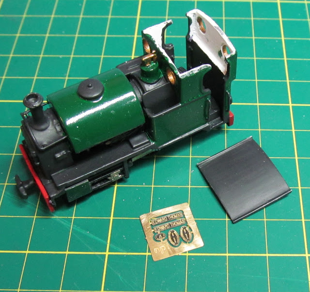
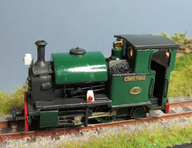
Paintwork on this model was completed when it was fully assembled, apart from the cab roof which was left loose to allow the cab interior to be finished. To prime the metal and plastic structure I used a matt grey spray primer suitable for metal and plastic surfaces. The finishing paints where oil-based enamels. The green used was a mix of deep Brunswick green and light grey green. The black areas were a mix of matt black on the smoke box and funnel, the other areas being painted in a charcoal grey. I used a signal red on the buffer beams, whilst inside the cab was left in the grey primer finish. Small details such as pipework and safety valves were picked out in a brass metallic finish. The whole model was finished in either a matt varnish or satin clear varnish once details such as the works plates and name plates were fitted.
©  2018   David Hurst     All  Rights Reserved

The set of etched brass plates were supplied by Narrow Planet, who produce a set specifically for “Edward Thomas” from the Talyllyn Railway.     

©  2018   David Hurst     All  Rights Reserved

The engine crew was an adapted Dapol Line side work crew figure , with one leg shortened to suit the height of the footplate whilst still looking like a 4 mm scale figure. 


Sunday 4 November 2018

009 Atkinson Walker Rail cars


Updated 2022

©  2018   David Hurst     All  Rights Reserved

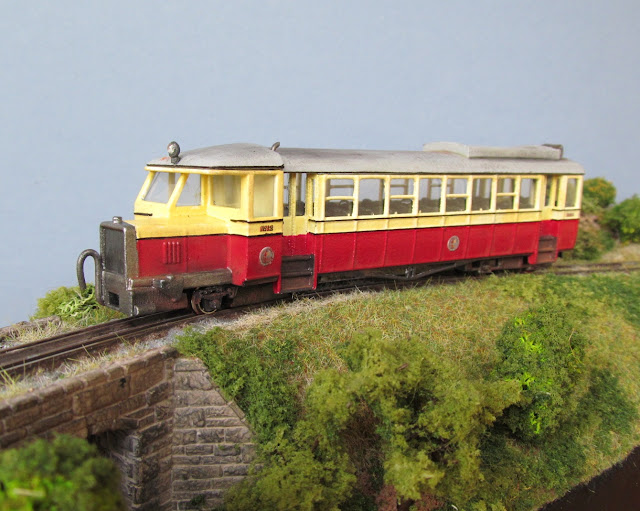
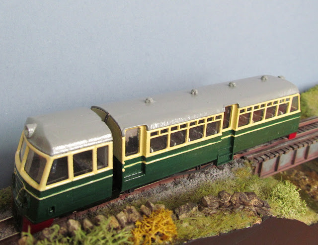
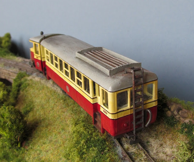
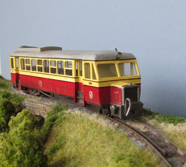
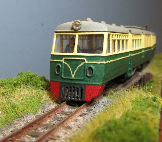
These are a series of rail car cabs and coach bodies which are based on the Atkinson Walker rail cars used on the County Donegal and West Clare railways in Ireland. The first one that I modelled, based on the articulated rail cars used on the County Donegal numbers 19 & 20, in turn, spawned several other versants based around units used in Australia and South Africa. 

©  2018   David Hurst     All  Rights Reserved

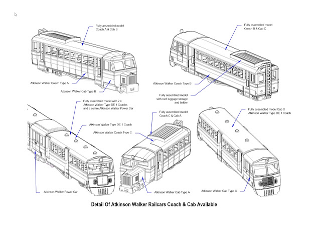
These included double-ended articulated rail cars and central power car units with coaches at each end. Even one special coach commission which was articulated at both ends with a cab at each end (Garret style).  

©  2018   David Hurst     All  Rights Reserved

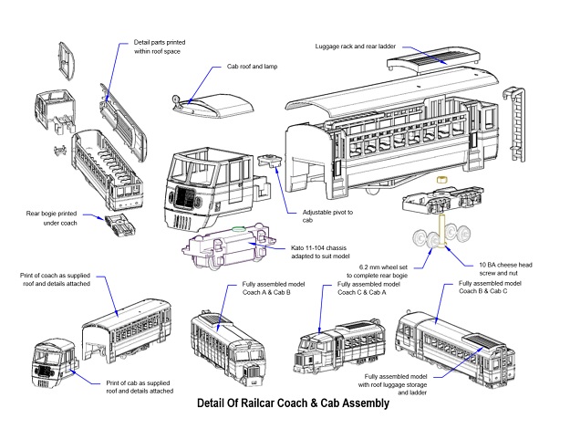
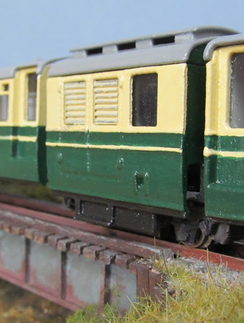
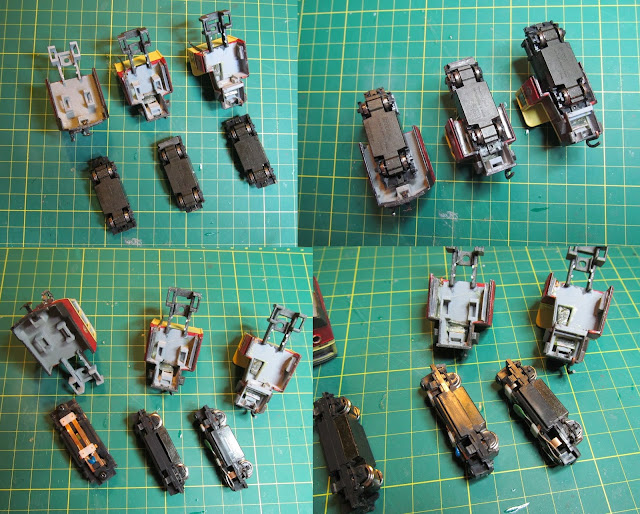
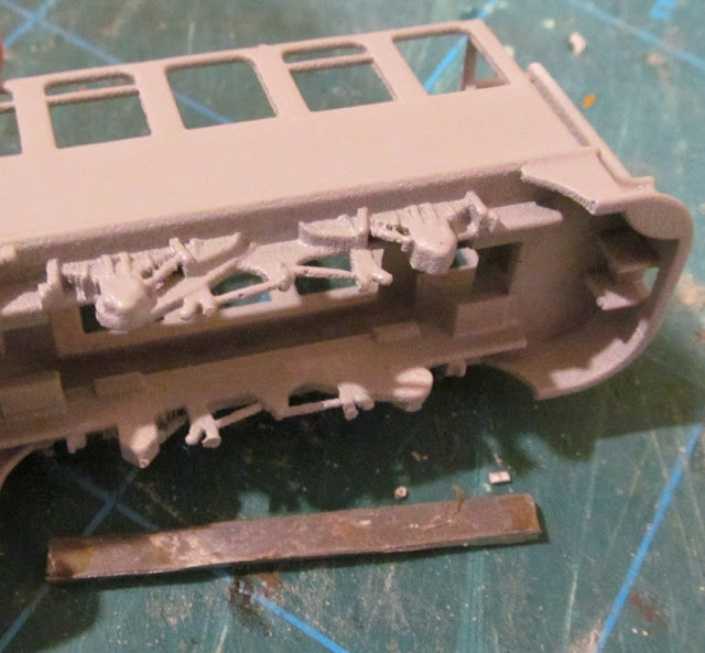
I then turned my attention back to the earlier versions used on the County Donegal railway: number 18 with the bonnet and flat cab front, number 12 with the staggered cab front looking very similar to a bus. I also looked at the coach bodies and have come up with an older panelled version with a different window arrangement. My final idea was to bring the ex- Clogher Valley Number 10 coach body into this range, which would give a smaller rail car for some of the space-challenged layouts out there. Since they all have the same coach body profile and pivot details each coach and cab can be interchanged, and they are all powered by the same Kato 11-104 chassis with some modifications to suit the various cab formats.

©  2018   David Hurst     All  Rights Reserved

These new rail cars are 4 mm scale, though the length of the coaches have been reduced to allow them to operate on smaller “Set Track” curve radiuses with more ease. Due to the cost of printing the coach bodies, I have designed them to print in Versatile Processed Plastic though I have made other options available. The Versatile Processed Plastic material is smooth looking on the mainly large flat surfaces of the coaches when the surface has a good build-up of primer. The cabs have a little more detail and can be printed in the Fine Detailed plastic if required. The main advantage of printing the coach in the Versatile Plastic is the bogie will be better suited to fitting and running the wheels. The Fine Detailed plastic does work but is brittle and would need more clearance forming to allow for the wheel bearings to be positioned in the bogie frame.

©  2018   David Hurst     All  Rights Reserved

These are simple models to build; the most challenging bit to work on it is the glazing. I have used acetate from old packaging to glaze the units that I have worked on. This is flexible and easy to cut, it can be bent at 90° or shaped into curves as required and it holds that shape very well.

©  2018   David Hurst     All  Rights Reserved

The coach glazing is held in place mainly by the seat sides or backs. There is a small gap at the end of each seat up to the inside of the windows which traps the thin glazing material. The top of the glazing is made ridged by allowing extra material to be left on the top and folded to form an angle, which is then held in place with spots of contact adhesive on the top edge. 

©  2018   David Hurst     All  Rights Reserved

Glazing the cabs was a more challenging task. I found that making a template was the best option for these shaped windows, in most cases if the glazing was a good fit it stayed in place. I added a small spot of contact glue at the top or on the flat area below the windows just to hold them in place.  
                   
©  2018   David Hurst     All  Rights Reserved

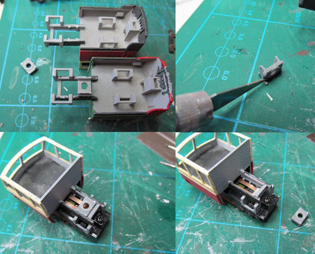
The Kato 11-104 or the new 11-110 chassis is straight forward to fit on the cads B & C. There is a little more cutting to do for the cab type A as it is slotted in at the front and the original clips are used at the rear of the chassis. 

©  2018   David Hurst     All  Rights Reserved

The pivot plate is printed under the frame on spurs. This is cut off its spurs and added to a groove in the top of the frame, the further back you place this, will allow the articulated bus body to work on tighter curves, but leaves a bigger gap between the bus and the cab, so this will allow the two to be finely adjusted to suit individual modellers needs before final fixing. Like a lot of things, it is a compromise between looks and functionality.

©  2018   David Hurst     All  Rights Reserved

I have designed the rear bogies on these models to be printed in Versatile Plastic as this will flex to allow the wheelsets to be put in place. It is, however, possible to print the models in the Fine Detailed Plastic; more clearance will be needed to allow the wheelsets to be fitted. I have done this by filing a Vee in the base of the bogie axle boxes up to the cone bottom.  
The axle’s pockets were polished smooth with a pointed flat bit; this was ground to match the cone shape formed on the inside of the axle boxes. I kept gently working the drill on each cone and then trying the wheel until I achieved smooth and free running. This has the effect of polishing the cone rather than drilling it out more.

©  2018   David Hurst     All  Rights Reserved

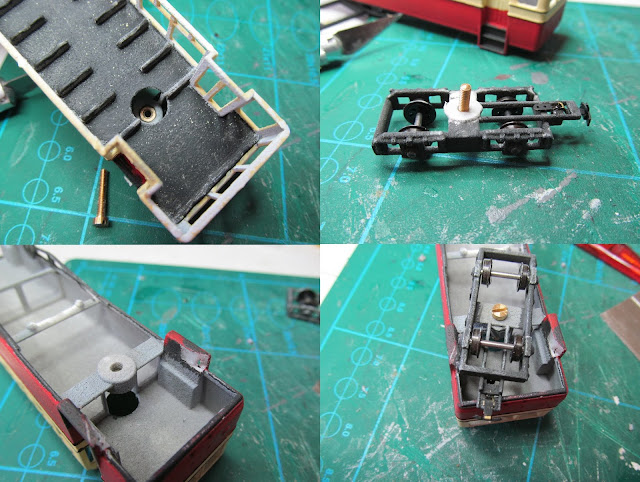
A pilot hole is formed in the bogie, this act as a guide for the clearance hole needed for an 8 BA cheese head machine screw used as a pivot. An 8 BA nut is located in a socket at the bottom of the coach body. The NEM coupling pocket can be attached to the rear of the bogie were a rectangular hole is formed to accept this, ones glued in place and allowed to set, file smooth any protruding material from the NEM coupling as this will catch on the lower part of the coach body.

When assembling the bogie to the body of the coach a washer of thin Plasticard needs to be used to give the right gap between the bogie and bodywork and allow for free movement between both. On some layouts with tight radius curves, it may be advisable to allow for more clearance on the back of the bogie. To achieve this I cut a small triangular section off the inside rear of the steps.

The wheels for these units were all 6.2 mm diameter but a mixture of Dundas models and Peco types. The metal axle and rimmed Dundas model wheels did seem to have the running edge but both worked well enough.

©  2018   David Hurst     All  Rights Reserved

Ballast was added to the coach body above the rear bogie in the form of two strips of lead sheet bonded to the base of the interior with contact adhesive. The cab also had ballast added to under the bonnet area and to the inner face of each side of the cab or inside the cab behind the driver’s location. 

Hugo Baart has very kindly sent a great picture of a different combination using a cab type C with a coach body type C, to come up with a more modern but short railcar combination. He has made some additions to the basic prints, like the grill, windscreen wipers, exhaust, luggage boxes, front and rear lights and interior lights. Also a soundecoder has been installed.
It will be fantastic addition to Hugo's layout "De Niggende Saligheyd".

©  2022   Hugo Baart     All  Rights Reserved


If you would like a copy of this model it is available on Shapeways at Model Engine Works:


Sunday 28 October 2018

009 Industrial Diesel


©  2018   David Hurst     All  Rights Reserved
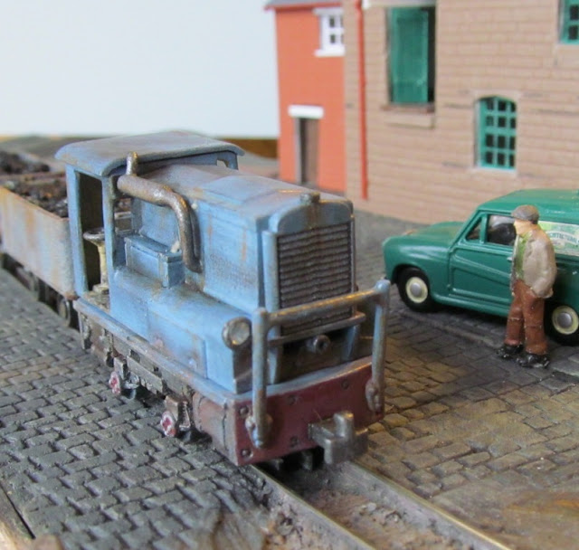
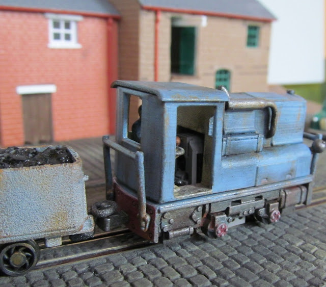
This is a small industrial loco based on the one used at the Guinness Brewery in Dublin. It is now an exhibit at the Ulster Folk and Transport Museum which is situated in Cultra near Belfast. 

My idea was to find a small to medium size industrial loco with an interesting look about it, I wanted a compact design where the cab was low enough to be used for both industrial and mining purposes. The one used at the Guinness Brewery in Dublin fitted this model very well, being designed to be used within the tight clearances around the Brewery complex in Dublin. 

The other good point about this engine was that it was no plain Jane; it had a good level of detail both under the footplate and around the bodywork. This is very good for adapting the design to suit a particular chassis. With the small size and narrow wheel base of this engine I have looked at using the Tomy-tec H1 chassis. It has turned out slightly larger than I planned, more on the medium size, but looks as if it is man enough to do most types of industrial haulage jobs. 


©  2018   David Hurst     All  Rights Reserved
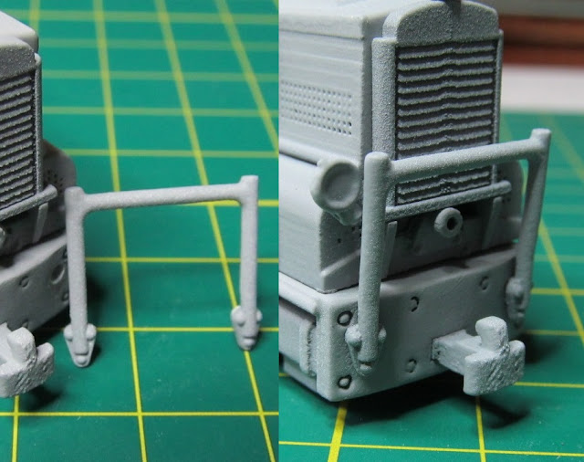
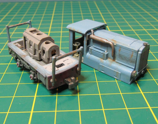
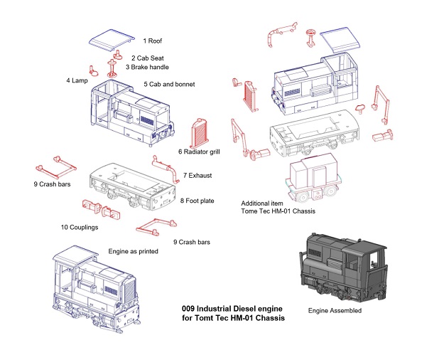
The model is printed in separate parts: the footplate, (which could be the basis of a different model) the body, the roof and the radiator. There are also smaller details printed within the body and footplate, including  an exhaust system crash bars, work lamp, brake handle, and cab seat. Some generic couplings are also included, but other types can be used also.

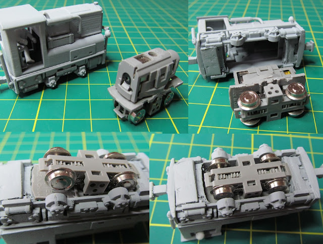
The Tomy Tec HM-01 chassis I have used needed to have its footplate reduced in width so I dismantled the chassis and cut the footplate down. This is much easier to do and a neater job is achieved. It all just clips back together again.


©  2018   David Hurst     All  Rights Reserved
Because of the engines size and the level of detail it is only suitable to print in the Fine Detailed Plastic.

©  2018   David Hurst     All  Rights Reserved

When using the Find Detailed Plastic form Shapeways the first thing I do before removing any of the parts is the soak the print in a paint remover / petroleum sprits (white sprits in the UK). This is to remove the wax support residue left from printing, and then a wash in warm soapy water should leave the surface ready for painting after it is fully dried.

©  2018   David Hurst     All  Rights Reserved
I use a grey or white spray primer to prep the model for finishing. In some areas it will be necessary to remove print lines from the surface. These sometimes only show up after the primer is applied and can be removed with a burnishing tool.  I use a hardwood stick with a rounded point to get in the tight spaces. Further light coats of the primer will give a good working surface on which to apply the finishing coats of paint .

©  2018   David Hurst     All  Rights Reserved
At this stage it is time to separate all the detail parts from the main body and footplate of the model. Most of the small parts will snap off the sprues with a genital push or twist, as the base of the sprues are smaller and weaken to allow for this. The main parts however are best cut from each other using a razor saw.

There may be a little more cleaning up to do on these small parts now that they are accessible all-round. Once this is done check that they all fitted into the corresponding holes made for them on the body of the engine. The fiddly ones are the driver’s seat and the brake handle column, for which I used small tweezers to hold the parts while putting them in place.
The chassis was tried in place next. I have allowed a little bit more clearance on this model than some of my previous ones, so the chassis will seem loose. This is because the Fine Detailed plastic is less flexible and would break if put under too much pressure. The use of a small piece of Blu Tack at each end of the chassis footplate will take this tolerance up.
©  2018   David Hurst     All  Rights Reserved
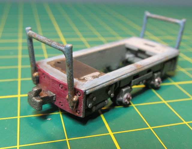
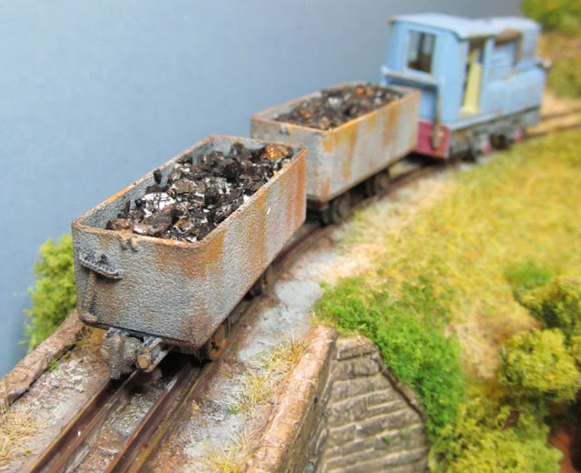
I found it easier to paint the small detailed parts before fitting them to the model. It also made the body and footplate much more accessible to paint in detail. I used Revel 09 charcoal on the chassis and a light blue mix on the bodywork. The cab interior had a thinned wash of a cream mix which included the brake column and driver’s seat. The buffer beams and axle boxes had a wash of bright red over the grey primer so that the grey showed through. I did not want the paint to look new but worn. I added rust streaks down various parts of the body work, from the corners of window and bonnet doors hinges and the radiator brackets. Soot and grime were added using a black and brown thinned wash applied with a dry brush, which helped to pick out areas like the side and front grills. Bare metal and metal components were picked out with a mixture of dark grey and silver (gunmetal). To finish the whole model was given a coat of satin varnish.

©  2018   David Hurst     All  Rights Reserved
The ballast was added to the model wherever I could find space, some each end of the foot plate and some centrally over the chassis. I could have but more in the front of the body behind the radiator but that would make the model imbalanced.

©  2018   David Hurst     All  Rights Reserved
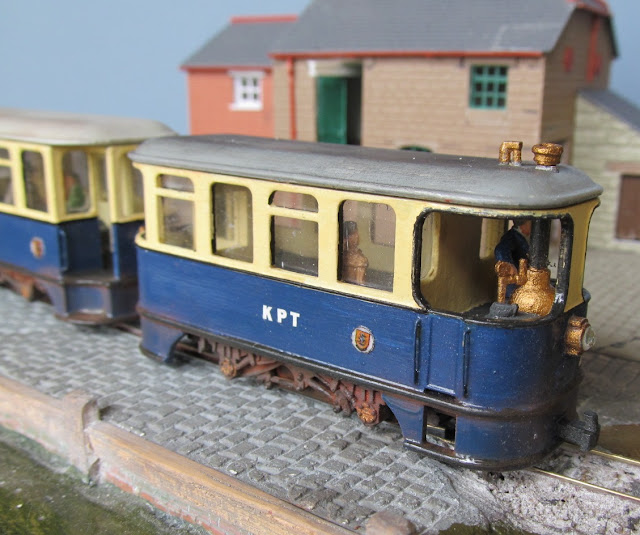
I found it difficult to find a driver for this particular little engine because of the seated and twisted position the figure would need to take. So I found a suitable Dapold line side figure and adjusted its posture to seating with arms out and head turned to the left. As these figures are on the tall side the loss of a bit of height did not seem to look out of place. 
©  2018   David Hurst     All  Rights Reserved

©  2018   David Hurst     All  Rights Reserved

    
If you would like a copy of this model it is available on Shapeways at Model Engine Works:


Monday 15 October 2018

009 Hoppers - Skips and Tubs


(4 mm Scale)
Designed to print in Black Versatile Plastic 


©  2018   David Hurst     All  Rights Reserved

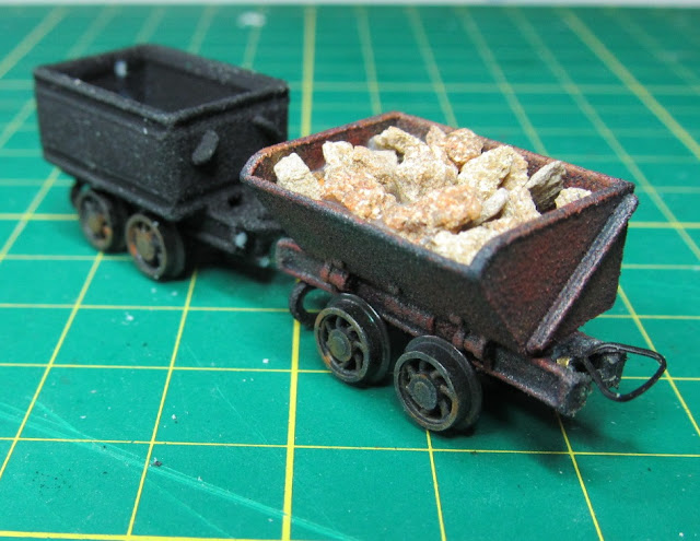
These small wagons started out as a 3D printing job for Unity Gifts http://www.unitygifts.co.uk/  who  wanted a pattern for moulding a small ore wagon which  was used by a Luxembourg ore mine. After doing this work I was left with a drawing of a neat little wagon, quite different from the typical Vee tippers that seem popular. I decided to do a little rework to develop them for use as 009 models.

©  2018   David Hurst     All  Rights Reserved

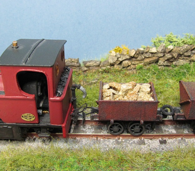
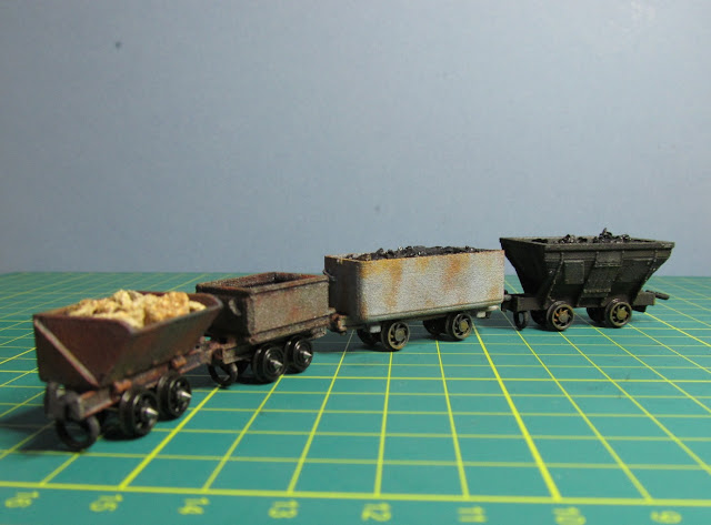
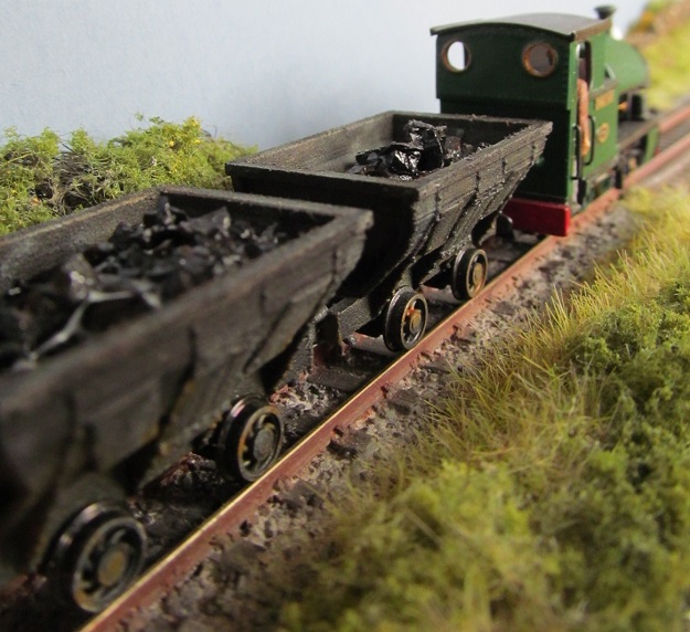
After several prototypes and a few suggestions, the basis of a series of small wagons has evolved. Using the same basic wagon frame and wheel arrangements with different bodies, I have come up with a varied selection of different small wagons. So far these include a wooden coal hopper, the original ore skip and two types of metal coal tubs. Perhaps more could be suggested? Their size and simple looks mean it would be possible to use them for 3 mm scale also.    

©  2018   David Hurst     All  Rights Reserved
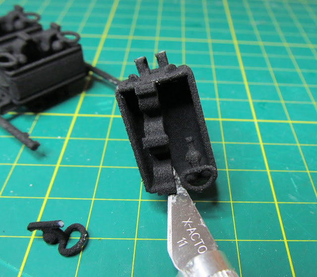
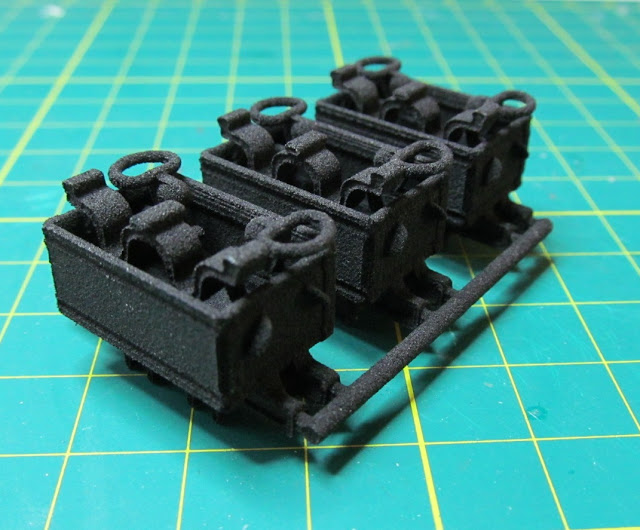
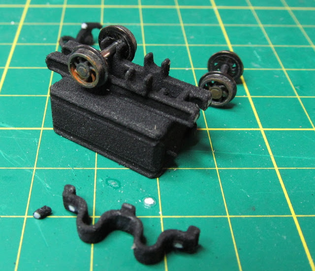
The wagons are generally all printed in blocks of 2 or 3 held together with rods and sprues and all the parts should be removed before assembly. The wheel clip and the couplings are printed inside the bodies and are easily removed by using a craft knife to cut the connecting sprues between the part and the wagon body. The sprues can then be trimmed back flush with the body sides. The wagons are connected by rods at each end, sprues attaching them to each of the wagon frames. Again, these are cut flush with the end of the frames.
©  2018   David Hurst     All  Rights Reserved
The little ore wagons are different in having a body that is also removed and can be reattached in a tipping position as well as in the loaded position. This was a good idea suggested by a fellow modeller.  

©  2018   David Hurst     All  Rights Reserved
They are all assembled in a similar fashion, first the wheels are altered to remove the needle point bearings. I have formed a small jig to hold the wheel while I remove the metal point with a small flat file. Much easier than trying to hold them with your fingers. The wheels are then poisoned in the U-shaped saddles and checked for free running. Sometimes a rub with a round file will smooth the rough surface of the plastic to allow better running of the wheels. The base plate is then fitted to hold the wheels in place. This is a clip in place item on most, only the coal hopper has a push fit plate. I have found that some easing of the clips is necessary depending on the print.
©  2018   David Hurst     All  Rights Reserved
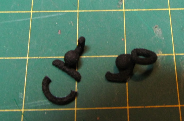
The only other items to fit are the couplings. If you use the universal ones they have both the hook and eye with a ball between and it is a simple matter of reversing the coupling at each end of the wagon.  The ball fits into a split socket at the end of the frames. 

©  2018   David Hurst     All  Rights Reserved
I have found that it is a good idea on the hook to cut off the ring on the eye leaving the cross bar which fits under the lower part of the frames and stops the hook twisting out of alignment.

©  2018   David Hurst     All  Rights Reserved
It is advisable to add a small amount of ballast to the bottom of the body of each wagon to help with smooth running. The load can be added above this either on a base or just fill the body with coal or rock / ore, them fix in place with some clear PVA glue.

©  2018   David Hurst     All  Rights Reserved
Finishing most of the wagons is done by dry brushing red rust, brown and a little silver to the surface of the metal wagons. On the wooden hoppers I used two shades of brown and a little gunmetal metallic to the metal straps with a small amount of rust colour round these also. The Hudson tubs were finished in a grey wash with shades of rust dry brushed on the sides.

©  2018   David Hurst     All  Rights Reserved
If you order the wagons in the White Versatile Plastic, it is possible to use an acrylic cloth dye to colour them in a similar manner to Shapeways. The product is Rit water based dye which was recommended on the narrow gauge forum by “TeBee” Tom Bell, but this is only suitable for the Versatile type plastic prints.
https://www.ritdye.com/products/cocoa-brown-powder/
©  2018   David Hurst     All  Rights Reserved

If you would like copies of these models they are 
available on 
Shapeways at 
Model Engine Works:


Sunday 12 August 2018

009 K.P. Tramcars


©  2018   David Hurst     All  Rights Reserved 

009 K.P. Tramcars

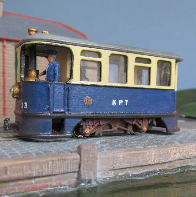
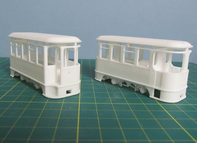
These are what might have been “tramcars”. One is a vertical boiler style steam tramcar, based on an Atkinson Walker steam wagon, combined with a generic electric tramcar, the other a generic double ended electric style tramcar which can be seen in many locations worldwide and can also be used as a dummy car or coach. The tram may have been used on some of the smaller country or seaside tram lines, which were looking for an economical passenger or mixed traffic tractor around the turn of the 19th century.

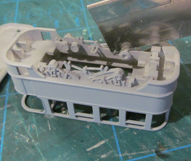
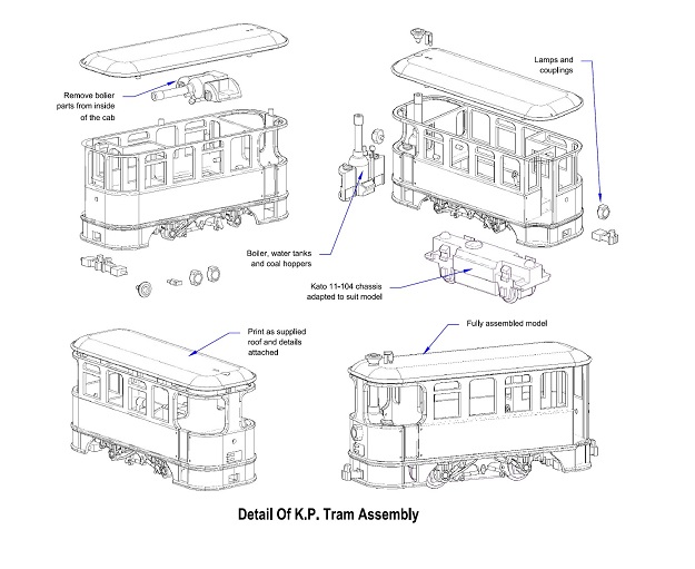
Both tramcars have been designed to use the Kato 11-104 chassis with some modification. The roof is removable to allow interior details to be added, and they also have some detailed parts printed with the model. These include a representation of a vertical boiler whistle, funnel cap, (K.P. steam tram only), running lamps, and a pair of couplings (on both trams).


©  2018   David Hurst     All  Rights Reserved 

The coach or dummy car which can be used as an electric tram or a small coach to pull along behind the K.P. steam tramcar or a suitable engine can run on the Kato 11-104 chassis or a dummy free wheeler chassis.  
   
Cleaning and priming
If you have a print in Smooth Fine Detail Plastic it is advisable to soak in petroleum spirits (paint thinners/cleaner). This is to remove the oil based wax support residue left from printing. Next wash in warm soapy water and allow to fully dry which should leave the surface ready for painting. I use a grey or white spray primer to prep the model for finishing,  but in some areas it will be necessary to remove print lines from the surface, and this can be done with a burnishing tool. I use a hardwood stick with a rounded point to get in the tight spaces.


©  2018   David Hurst     All  Rights Reserved 

Wirework

There is not a great amount of wirework on these models, just the hand rails each side of the cab door openings and at the passenger’s entrance. For this I have used 0.45 mm brass wire, and drilled out the pilot holes to suit. The cab handrails are formed as four U shaped pieces which I pushed through the pre-drilled holes from the outside and fixed with Cyanoacrylate glue (super glue). The passenger’s entrance has one U shaped piece and one full height pole fitted between the floor and roof. This can be fitted when the roof is fixed in place.


©  2018   David Hurst     All  Rights Reserved 

Fitting the chassis & ballast

The Kato chassis will need to be cut down to fit, the coupling mounts need to be cut off each end and the axel boxes will need to be removed from the sides. I have added two small lead weights at each end of the chassis glued in place, also some strips of lead inside the cabin to each side of the chassis opening. This has been enough ballast to give the model good electrical pick up and traction. 

Couplings

A Pair of printed couplings are supplied with these models. They are printed under the footplate, along with the other small detail parts such as the work lamps.


©  2018   David Hurst     All  Rights Reserved 

Glazing
For the windows I have used thin acetate saved from old packaging; this is glued with Cyanoacrylate glue (super glue). It is great if you have curved or awkward shaped glazing  as the acetate being thin and flexible can be persuaded to take on a curve by passing it between a smooth round surface like a screw driver shaft and your thumb. I fit the glazing when building the model and then fix it in place in the final stages after the painting is completed and before the roof is fitted. Any weathering is done after the glazing is completed.  
 

Interior details

The K.P. steam tram has a vertical boiler; water tanks, feed pipes and gauge printed within the passenger cabin. This will need removing and then details such as wheel valves and additional pipework can be added. This type of small tram is likely to have had side benches for passenger seating, so figures adjusted to suit the internal floor level can be added with their backs to the windows to represent passengers.       


©  2018   David Hurst     All  Rights Reserved 
    
Painting

After initial preparation of the model it was given a couple of light coats of matt grey primer, then burnished and smoothed, with a final coat of primer to finish off.  As there is no prototype to guide us with this model, I chose to do the footplate, roof and handrails, in a charcoal grey Revel No 09. I dry brushed a little silver round the mechanical parts under the footplate which highlights the details; also some gloss varnish gives the impression of oil on these areas. The body on these models have been done in yellow cream at window level and a dark blue below. The impression of rust was added to some areas of the footplate, buffer beams and running gear with a dry brushed application of Revel Matt No 37 and No 85.    

The final little bit of detail was to add the work lamps and lenses. For these I used 3mm Clear Rhinestones, fitted after painting was completed..
I finished over all areas with a coat of matt varnish. I then added weathering with powdered wax pastels, using mixes of orange, brown and black, to give the tram an overall weathered and well- used appearance.  


©  2018   David Hurst     All  Rights Reserved 


©  2018   David Hurst     All  Rights Reserved 

©  2018   David Hurst     All  Rights Reserved 


If you would like a copy of this model it is available on Shapeways at Model Engine Works: