Showing posts with label Kato 11-104 chassis. Show all posts

Sunday, 10 March 2019

009 Skylark Style Engine


3D print of this engine is now available at Model Engine Works on Shapeways.


©  2019   David Hurst     All  Rights Reserved

One small engine which a lot of people seem to have on their layouts is the Kerr Stuart 0-4-2 Skylark. Most use the white metal kit and a chassis such as the Ndrive 0-4-0 with a pony wheel added. I was impressed by the one built by Michael Campbell using the Kato chassis with side plates which mimicked the pony wheel with the rear wheel of the Kato chassis, a simple but really good solution. http://michaelsrailways.blogspot.co.uk/2012/10/a-little-bit-of-skirt.html

©  2019   David Hurst     All  Rights Reserved

I decided to have a go at scratch building my own version of the Skylark. As I was looking to build something in this style rather than recreating the actual engine, there were possibilities to make a few changes to the model and still keep the look and spirit of that style of engine.
I got as many reference pictures as I could find together and also one of the Kato 11-104 chassis. 

©  2019   David Hurst     All  Rights Reserved

These are very good when getting into modelling 009 narrow gauge engines as they are so reliable and inexpensive. These can be used on engines that are made with side plates, which were usual on roadside tramways built in the UK and Ireland.
I started by making a mock-up footplate, to get the right-sized opening to fit the chassis. Once I had that sorted I made a few scale drawings of the bodywork, using the pictures as guidance.

©  2019   David Hurst     All  Rights Reserved

My plan was to build the engine from different thickness of sheet Plasticard and spare pieces from old model kits that had been left over. 
To make the body I printed some paper patterns from the drawings that I had made, which were temporally fixed to various thickness of Plasticard with Pritt stick. This holds them long enough to cut out and the paper then just peels off afterwards.
The smoke box having a round top was formed using 1mm front and back shaped pieces fixed to the rectangular base. Then thin sheet Plasticard was formed over this in two layers. This is easy to bend to shape and by gluing the additional layer strengthens it up. The same idea was used on the boiler, with an additional layer being used to create the bands around the boiler. Of course if you have the right size tube this will save going to the trouble of making the boiler.
The chimney and dome were made using lime wood and turned in the chuck of a small electric drill.

©  2019   David Hurst     All  Rights Reserved


If I had known about the “Gem 9104” white metal OO-9/ industrial loco fittings beforehand I would have used one of these chimneys and the dome.

The smoke box door was made up of two discs of 1 mm Plasticard sanded to shape, the hinges and handles were added using spare bits from an Airfix 040 saddle tank kit.I formed the spectacle windows by drilling an oversized hole and lining this with strips of thin Plasticard sheet to give the impression of a brass frame when painted. I made use of a pair of vacuum pipes from a spare Vale of Rheidol coach.  
 
©  2019   David Hurst     All  Rights Reserved


The upper edges to the water tanks have a strip of the Plasticard added round the top  and this is then filed to a D shape with the top inner edge softened, which forms a slight well at the top of the two side tanks.
I used one of the Dapol track side figures for the crew. I did find that I had to shorten the legs on this figure as in general they are slightly over size in some of the smaller engines.  
©  2019   David Hurst     All  Rights Reserved

I made the lamps in bulk some time ago using white 1 mm thick plasticard rectangles to form a 3 x 2 x 2mm block and then added a 2mm disk on top, and for the lenses I used a small 2mm clear or red rhinestone. 
The paint was a mixture of various Humbrol colours to produce a shade of maroon that I liked. A final coat of matt was added to the footplate and smoke box, then satin varnish over the maroon painted areas. I used real crushed coal in the bunker – you need to get this almost like dust at this scale to look right.

©  2019   David Hurst     All  Rights Reserved

The finishing touch was a set of name and works plates from Narrow Planet who do the brass etched plates to order. “Fergus” was my chosen name with a separate set of works plates.

©  2019   David Hurst     All  Rights Reserved

 It has been a good practice run for me and I have enjoyed the challenge of the build.


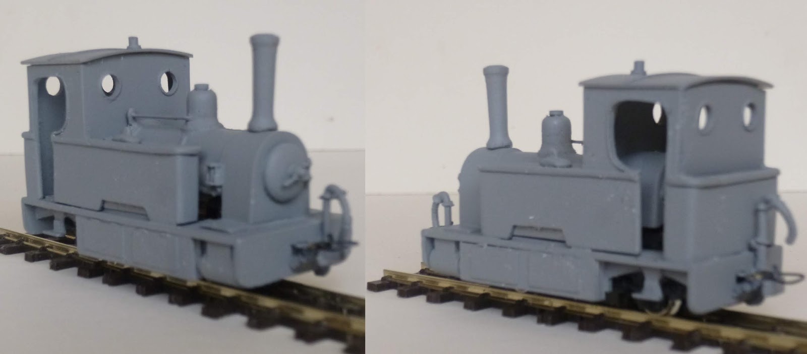
This popular little engine is now available as a 3D print to run on the readily available Kato 11-104 chassis. It has separate foot plate body and roof to allow for interior details to be added, there are also a pair of simple couplings printed under the foot plate of the model.
Additional details will be needed to complete the model as show, these include smoke box door handles, cab side handrails and working lamps.

©  2019   David Hurst     All  Rights Reserved

If you would like a 3D print of this model visit Shapeways at:


Sunday, 4 November 2018

009 Atkinson Walker Rail cars


Updated 2022

©  2018   David Hurst     All  Rights Reserved

These are a series of rail car cabs and coach bodies which are based on the Atkinson Walker rail cars used on the County Donegal and West Clare railways in Ireland. The first one that I modelled, based on the articulated rail cars used on the County Donegal numbers 19 & 20, in turn, spawned several other versants based around units used in Australia and South Africa. 

©  2018   David Hurst     All  Rights Reserved

These included double-ended articulated rail cars and central power car units with coaches at each end. Even one special coach commission which was articulated at both ends with a cab at each end (Garret style).  

©  2018   David Hurst     All  Rights Reserved

I then turned my attention back to the earlier versions used on the County Donegal railway: number 18 with the bonnet and flat cab front, number 12 with the staggered cab front looking very similar to a bus. I also looked at the coach bodies and have come up with an older panelled version with a different window arrangement. My final idea was to bring the ex- Clogher Valley Number 10 coach body into this range, which would give a smaller rail car for some of the space-challenged layouts out there. Since they all have the same coach body profile and pivot details each coach and cab can be interchanged, and they are all powered by the same Kato 11-104 chassis with some modifications to suit the various cab formats.

©  2018   David Hurst     All  Rights Reserved

These new rail cars are 4 mm scale, though the length of the coaches have been reduced to allow them to operate on smaller “Set Track” curve radiuses with more ease. Due to the cost of printing the coach bodies, I have designed them to print in Versatile Processed Plastic though I have made other options available. The Versatile Processed Plastic material is smooth looking on the mainly large flat surfaces of the coaches when the surface has a good build-up of primer. The cabs have a little more detail and can be printed in the Fine Detailed plastic if required. The main advantage of printing the coach in the Versatile Plastic is the bogie will be better suited to fitting and running the wheels. The Fine Detailed plastic does work but is brittle and would need more clearance forming to allow for the wheel bearings to be positioned in the bogie frame.

©  2018   David Hurst     All  Rights Reserved

These are simple models to build; the most challenging bit to work on it is the glazing. I have used acetate from old packaging to glaze the units that I have worked on. This is flexible and easy to cut, it can be bent at 90° or shaped into curves as required and it holds that shape very well.

©  2018   David Hurst     All  Rights Reserved

The coach glazing is held in place mainly by the seat sides or backs. There is a small gap at the end of each seat up to the inside of the windows which traps the thin glazing material. The top of the glazing is made ridged by allowing extra material to be left on the top and folded to form an angle, which is then held in place with spots of contact adhesive on the top edge. 

©  2018   David Hurst     All  Rights Reserved

Glazing the cabs was a more challenging task. I found that making a template was the best option for these shaped windows, in most cases if the glazing was a good fit it stayed in place. I added a small spot of contact glue at the top or on the flat area below the windows just to hold them in place.  
                   
©  2018   David Hurst     All  Rights Reserved

The Kato 11-104 or the new 11-110 chassis is straight forward to fit on the cads B & C. There is a little more cutting to do for the cab type A as it is slotted in at the front and the original clips are used at the rear of the chassis. 

©  2018   David Hurst     All  Rights Reserved

The pivot plate is printed under the frame on spurs. This is cut off its spurs and added to a groove in the top of the frame, the further back you place this, will allow the articulated bus body to work on tighter curves, but leaves a bigger gap between the bus and the cab, so this will allow the two to be finely adjusted to suit individual modellers needs before final fixing. Like a lot of things, it is a compromise between looks and functionality.

©  2018   David Hurst     All  Rights Reserved

I have designed the rear bogies on these models to be printed in Versatile Plastic as this will flex to allow the wheelsets to be put in place. It is, however, possible to print the models in the Fine Detailed Plastic; more clearance will be needed to allow the wheelsets to be fitted. I have done this by filing a Vee in the base of the bogie axle boxes up to the cone bottom.  
The axle’s pockets were polished smooth with a pointed flat bit; this was ground to match the cone shape formed on the inside of the axle boxes. I kept gently working the drill on each cone and then trying the wheel until I achieved smooth and free running. This has the effect of polishing the cone rather than drilling it out more.

©  2018   David Hurst     All  Rights Reserved

A pilot hole is formed in the bogie, this act as a guide for the clearance hole needed for an 8 BA cheese head machine screw used as a pivot. An 8 BA nut is located in a socket at the bottom of the coach body. The NEM coupling pocket can be attached to the rear of the bogie were a rectangular hole is formed to accept this, ones glued in place and allowed to set, file smooth any protruding material from the NEM coupling as this will catch on the lower part of the coach body.

When assembling the bogie to the body of the coach a washer of thin Plasticard needs to be used to give the right gap between the bogie and bodywork and allow for free movement between both. On some layouts with tight radius curves, it may be advisable to allow for more clearance on the back of the bogie. To achieve this I cut a small triangular section off the inside rear of the steps.

The wheels for these units were all 6.2 mm diameter but a mixture of Dundas models and Peco types. The metal axle and rimmed Dundas model wheels did seem to have the running edge but both worked well enough.

©  2018   David Hurst     All  Rights Reserved

Ballast was added to the coach body above the rear bogie in the form of two strips of lead sheet bonded to the base of the interior with contact adhesive. The cab also had ballast added to under the bonnet area and to the inner face of each side of the cab or inside the cab behind the driver’s location. 

Hugo Baart has very kindly sent a great picture of a different combination using a cab type C with a coach body type C, to come up with a more modern but short railcar combination. He has made some additions to the basic prints, like the grill, windscreen wipers, exhaust, luggage boxes, front and rear lights and interior lights. Also a soundecoder has been installed.
It will be fantastic addition to Hugo's layout "De Niggende Saligheyd".

©  2022   Hugo Baart     All  Rights Reserved


If you would like a copy of this model it is available on Shapeways at Model Engine Works:


Thursday, 30 November 2017

Phoenix


The C.D.J.C. Phoenix Diesel:

2020 Updates
©  2017   David Hurst     All  Rights Reserved


A Brief History

Built by Atkinson-Walker wagons Ltd of Preston in September 1928 as one of their Class A.3 engines. After a short trial by the Clogher Valley Railway, it was found to be totally unsuitable. By the end of 1929 Atkinson-Walker wagons Ltd had gone out of business, and with no buyer to be found the engine lay idle at Aughnacloy coach and wagon shed until 1932. It was bought by Henry Forbes for the County Donegal Railway and converted at the Great Northern Railway’s Dundalk workshop to diesel power. It was fittingly named the “Phoenix” and worked on the County Donegal Railway till its closure in 1959. It can now be seen in the Ulster Folk & Transport Museum.


Model Scales

This is an unusual engine both for its looks and how it came about, and makes a very suitable subject to model for a narrow gauge railway. It may not have skirts but the amount of detail at each side of the footplate does a good job of hiding whatever chassis is used. The initial model was drawn up in 4 mm scale to suit the Halling motor bogie at either 12mm for 00n3 or 9mm for 009.


©  2017   David Hurst     All  Rights Reserved
A further version being produced to suit the Kato 11-104 chassis in 009, this has a slightly reduced overall size to help it to blend in with the 9mm track and not look too top-heavy.
I have made it available in both 00n3 and 009 versions to print in Frosted Ultra Detail. It should also be possible to print in Strong and Flexible if required. If a suitable chassis can be found it is planned to make it available in TTn3 3mm scale also.

With Frosted Ultra Detail it is advisable to soak in “White Sprits” (Petroleum organic solvent – paint thinners) in order to remove the wax support residue left from printing, then a wash in warm soapy water should leave the surface ready for painting after it is fully dried. I use a grey or white spray primer to prep the model for finishing. In some areas, it will be necessary to remove print lines from the surface, and this can be done with a burnishing tool - I use a hardwood stick with a rounded point to get in the tight spaces. Do these processes before separating the print into its component parts so you will be less likely to lose any of the small pieces.


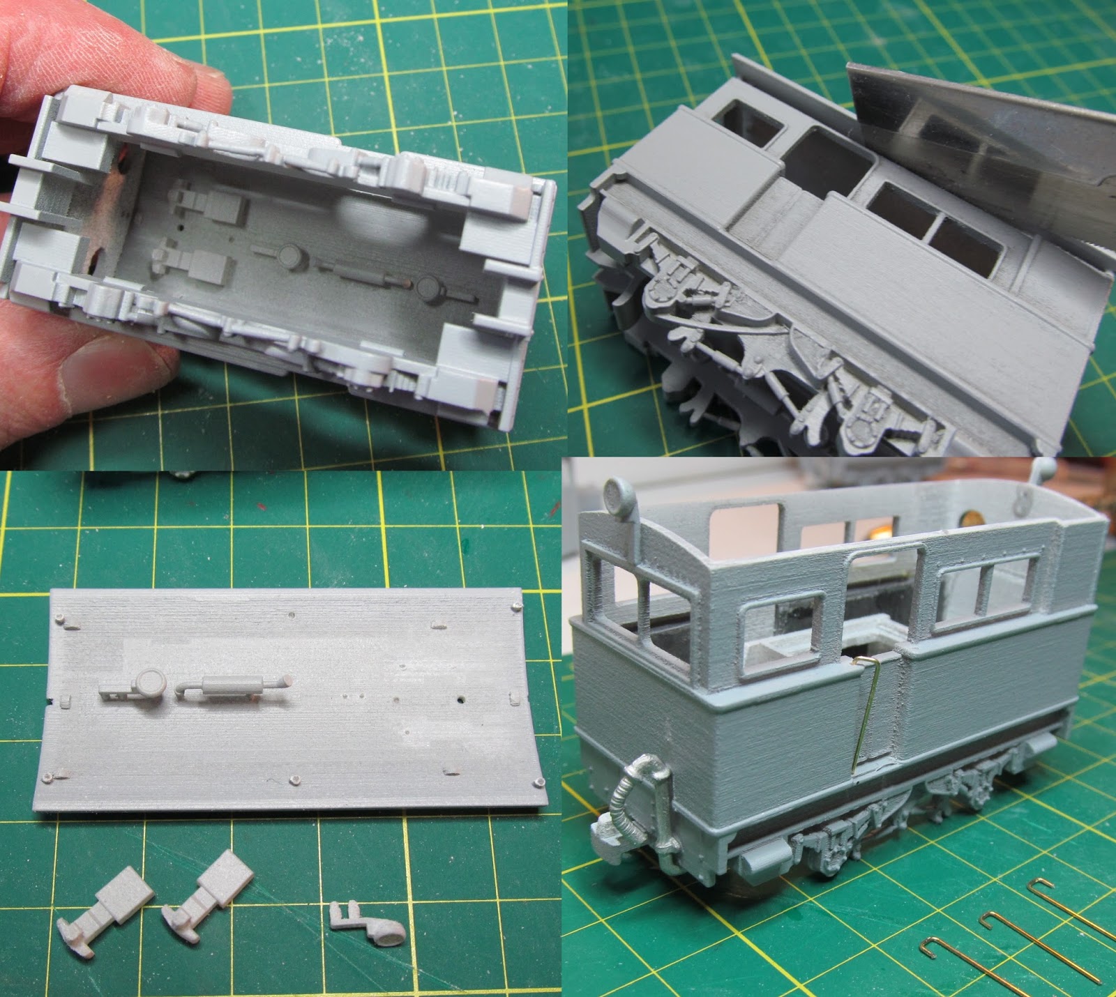
I have designed the bodywork and footplate in one, with the roof removable to allow for interior details and ballast to be fitted. A small exhaust and silencer, two work lamps and a pair of couplings are printed within the main body of the loco. These all need to be removed before the chassis is fitted. 

©  2017   David Hurst     All  Rights Reserved
Ballast
There are recesses in the sides to front and back of the cab openings which I have filled with lead sheet, at the front end (with the square windows) I have also added lead under the windows. This should give sufficient weight to the engine for traction and electrical pickup.

©  2017   David Hurst     All  Rights Reserved
 Fitting the chassis
With the Halling chassis it is a straight forward fit between the two pressure tabs front and back. It may be necessary to file a small amount off the inside of these tabs or add a shim on so you get a snug fit, but this depends very much on the printing process and is difficult to predict. The Kato chassis will need to be cut down to fit, the coupling mounts need to be cut off each end and also the axel boxes will need to be removed from the sides. I have added two small lead weights at each end of the chassis glued in place - this is not totally necessary but does keep the ballast low on the model.
©  2017   David Hurst     All  Rights Reserved
Wire-work
There is not a great amount of wirework on this model; just the handrails each side of the cab door openings. For this, I have used 0.45 mm brass wire and drilled out the pilot holes to suit. They are, however,  not straight: the tops are turned to 45° outward, this makes them look straight when they are viewed side-on. See picture which may explain this better. 
©  2017   David Hurst     All  Rights Reserved
Couplings
A pair of printed couplings are supplied with the models. On the 00n3 they are printed under the footplate while on the 009 they are printed under the roof, along with the other small detail parts such as the exhaust and work lamps. For the prototype models, I have used one printed and one Greenwich type coupling on the 00n3, and both printed on the 009 versions.

©  2017   David Hurst     All  Rights Reserved
Glazing interior details
For the windows I have used thin acetate saved from old packaging which is glued with a contact adhesive and is great if you have curved or awkward shaped glazing, being thin and flexible to use. I fit the glazing when building the model, and then fix it in place in the final stages after the painting is completed, and before any weathering is done.  
Vacuum pipes
These are white metal from a Vale of Rheidol coach; supplied in sets by Dundas Models. I used two of the smaller one on these models.
Painting
After initial preparation of the model it was given a couple of light coats of matt grey primer then burnished and smoothed, with a final coat of primer to finish off. A base coat of matt white was applied before the cream was added (the grey is too dark for a cream base coat). After this had time to dry I used a mix of Revel No 36 red and No 331 red burgundy on the lower part of the body. The cream on the upper bodywork was a mix of No 5 white and No15 yellow. The footplate, roof, handrails, lamps and windows were all done in a charcoal grey No 9. I dry brushed a little silver around the mechanical parts under the footplate which highlights the details; also some gloss varnish gives the impression of oil on these areas. The impression of rust was added to some areas of the footplate, buffer beams and running gear with a dry-brushed application of Revel No 37 and No 85.  
I have printed the C.D.J.C. logo on photographic semi-gloss print paper, which has allowed me to size and print to suit 4mm scale, and have then fixed it to the model with Cyanoacrylate (super) glue. The print is sealed with a coat of matt varnish which softens the edges fix the print and helps bond it to the finished model.
Graphic details
I have used 2mm white lettering for the “PHOENIX” name; these are from Fox Transfers ref F-G1003 Franklin Heavy 2mm & 1mm. With the aid of a piece of masking tape which had index marks for each letter I was able to place the individual letters straight and at the correct spacings on both sides of the cab, the “OE” arrangement being the fiddliest as the “O” is cut vertically and joined to the front of the “E”. The other point to note is that there are only two letter X’s on the Fox transfer sheet. As I was making two models this left me two short. I overcame this shortfall of letters by cutting the bottom leg of two of the Y’s and joined them together one part upside down.

©  2017   David Hurst     All  Rights Reserved
The number 11 plates on the upper cab sides were drawn to scale and I asked Narrow Planet to produce a pair of these brass-etched plates for each model. After painting the background in a matching red to the lower bodywork, the number plates were added to each side of the cab, fixed in place with the Cyanoacrylate (super) glue.   

©  2017   David Hurst     All  Rights Reserved
After adding the decals number plates and logos, the final little bit of detail to add was the work lamp lenses. For these I used 2mm Clear Rhinestones, fitted after painting was completed.
©  2017   Paul Titmuss     All  Rights Reserved
I finished overall areas with a coat of matt varnish. I then added weathering with powdered wax pastels, using mixes off orange, brown and black, to give the engine an overall weathered and well- used appearance.  

©  2017   David Hurst     All  Rights Reserved

In early 2020 Kato introduced there new and updated versions of their popular 11-103 and 11-104 chassis, these are now phasing out and being replaced by the 11-109 and 11-110. With this change, I have made some simple alterations to my models using these chassis.
 If you would like a copy of this model it is available on Shapeways at Model Engine Works:


Monday, 17 October 2016

J.C.R. Sentinel Steam Railcar Pioneer 1

Updated 2020 to also suit the Kato 11-110 chassis


The Pioneer 1 took its first trip on the Jersey Railway Company’s line on the 18th June 1923. The makers Cammel Laird had developed this type of railcar to run more economically for the smaller railways and branch lines.
The J.R.C. railcar was 56' 6" long and weighed in at just over 15 tons. It consisted of a steam tractor unit with a 2-cylinder engine controlled in the forward direction by the driver- come- fireman, and in the other direction, a guard had control. There was a capacity for 64 passengers seated in first or second class.
Three of these railcars were used by the J.R.C; their benefits were obvious in that they used 5lb of coal per mile, compared to the 25lb that the company’s engines used.
The model of this railcar was a commission by a colleague at work, who having made regular visits to Jersey had learned about the two railways that had once existed on the island. He had decided to model a layout based on the Jersey Western Railway after it was re-gauged from standard gauge to 3' narrow gauge early in its existence.
J.R.C ran four 2-4-0 tank engines for most of its lifetime, a fifth one proved too heavy for the track and being little used after the Great War was sold on. Three sentinel steam railcars were also employed from the early 1920s until the line’s closure in the mid-1930's.
This was a perfect opportunity to put into practice all I had learned in developing the 009-gauge version of the Clogher Valley Railway articulated railcar and apply it to something different. I would use the same basic set up of chassis and rear bogie as we were still working in 009 gauge for this layout.
We took the decision to scale the length down from the 56' 6" to something around 40' which we felt would work on the layout planned much better. 


I further adapted this and produced a shorter version still at around 33'. This was done by keeping the tractor unit the same and reducing the coach body. I plan to offer the smaller version for sale on Shapeways.


From the start, I had decided to develop this model to be printed in Strong White and Flexible Polished plastic as it suited our budget, and will still print in the more detailed Frosted Ultra Detail if we decide to later. The design being quite simple and uncluttered did make this a workable option. 

As off November 2017, we have made this model available on Shapeways in the Frosted Ultra Detail plastic.


This model is formed in two parts: a tractor unit, body and roof held together on spurs, and the coach in three parts; body, roof and bogie again kept together on spurs. I have allowed for the fitting of a Peco NEM coupling pocket on the front of the tractor, and the bogie also has a socket for one at the rear. On the prototype, a trailer was used at busy times so it may be an option to work on this later.  


A small change to the bogie on this model was to allow for the fitting of Kato 11-606 wheels, the axles on these being slightly narrower and the wheels being 0.6 mm smaller in diameter than my previous choice. This has meant repositioning the pivots in the axle box to suit the new wheels. The size of pivot screw and nut is 12BA x 1/2" long which in metric is 2mm diameter or M2 x 12mm long.


Using the trusty Kato 11-104 or new in 2020 the 11-110 chassis is a straight forward fit a small frame printed in the cab bodywork, which clips onto the chassis intended mounting points. 


The only modification to the chassis is that the two balconies including the couplings need cutting off. Again the pivot plate is loose in order to allow for adjustment between the cab and coach body to suit the curves on individual layouts. I have now modified this to clip in place so that when in use you are able to adjust the pivot centre to suit the curves on a particular layout. If you want it fixed it can still be glued in place.


Making the roof removable allows for interior finishing, the adding of glazing and figures, with a little more ease. I have incorporated the upper backs of the seats in the coach to add a little interior detail, though these are not as easy to finish within the body of the coach and it does bring the cost of the model down having fewer loose parts.
The tractor unit has an uncluttered interior into which some details can be added if required. There are small round hollows formed on the front of the cab for 2mm rhinestone beads to be added as lamps, which I like as they give a sparkle to the lamp that I cannot get with paint alone.


Separating the parts
My first job was to separate the bogie from the coach body and roof, then the cab body from its roof. I did this using a razor saw and because all the components are quite rigid this was not too difficult; once the parts are loose it is quite straightforward to remove the remaining spurs. I then went about priming all of the parts and removing any layering that was evident. Fortunately, the polishing process does do a good job in reducing this, so three or four thin priming coats sprayed on with a bit of burnishing with a hardwood stick between coats did the job.


Adding interior detail cab
As the cab is quite devoid of interior detail I decided to add a mockup of a two-cylinder engine boiler and the driver- come- fireman. With a little research on similar Sentinel units, I came up with a rough outline for the engine and boiler. This was pre-finished in a toned down black with a red flywheel and gunmetal details, then fitted into the cab along with the crew and glazing. Probably a lot more than is needed considering what can actually be seen. Well I know it’s there.          


Adding ballast
I add two narrow strips of lead to the cab section over the chassis, and two smaller strips to the bodywork of the coach each side of the rear bogie. This greatly improved the running of the whole unit and allowed it to pull a small trailer coach and a box van. 

Fitting the wheels and bogie
The chassis clipped into the mounts perhaps a little tightly so I eased this with a small file. It did not take a lot on this print but I do find that there are slight variations in the S.W.F. prints that cannot really be anticipated. The Kato wheels were again tight for the bearing cones, so I have a small flat bit adapted to polish the bearing cones out and make the surface smooth for the pins to run in. Even though I had the print polished these areas seem too small and tucked away to reach successfully.   


Painting of the railcar
I decided to paint the railcar in the later livery, though it is debatable as to the exact shades of yellow and green it was painted in. Mixing a pale mustard yellow (Humbrol Matt yellow 154 + white 34) and a toned down mid green (Humbrol Satin 131 + matt grey 106) looked a good combination, with a light to mid grey (Humbrol matt grey 106 + white 34) roof and toned down matt black (Humbrol Matt black 33 + grey 34) underframe bogie and steps. The interior was left in the mid grey primer that the whole model was based out in. I applied four thin coats of this matt grey primer which did improve the surface finish, filling most of the layering evident on the roof. As I was using a light finish colour, I applied a final priming coat of white after masking the windows from the inside. Once two thin brushes applied matt topcoats were applied, I added a finishing coat of gloss varnish before applying water slide transfers and the coach line, which I added with a Staedtler black permanent Lumocolor pen. A final coat of satin varnish over this to seal the whole model. I used a bit of black crushed up wax pastel to dirty the roof and some burnt umber to give the lower sides and running gear a used look. This was applied with a soft No 6 size paint brush, just rubbed in where needed. The good thing about using the wax pastels is that you can clean it off and re-apply if you like.    


Adding Glazing
This was done using some reclaimed acetate sheet form old packaging I had saved.    I made card templates of each section first to get the fit right, then cut and added the acetate, bonding this in place with contact adhesive.  


Final details
The final bits to be added were the handrails and the front whistle. These were done with 0.45mm brass wire bent to shape, suitable holes were drilled in the bodywork and the wire added, then superglued in place.        


I you like this model and would be interested in a print I will shortly be releasing 
it on the Shapeways market place at: