Updated 2022
 |
©
2018 David Hurst All Rights Reserved
|
These are a
series of rail car cabs and coach bodies which are based on the Atkinson Walker
rail cars used on the County Donegal and West Clare railways in Ireland. The
first one that I modelled, based on the articulated rail cars used on the
County Donegal numbers 19 & 20, in turn, spawned several other versants
based around units used in Australia and South Africa.
 |
©
2018 David Hurst All Rights Reserved
|
These included double-ended articulated rail cars and central power car units with coaches at each
end. Even one special coach commission which was articulated at both ends with
a cab at each end (Garret style).
 |
©
2018 David Hurst All Rights Reserved
|
I then turned
my attention back to the earlier versions used on the County Donegal railway: number
18 with the bonnet and flat cab front, number 12 with the staggered cab front
looking very similar to a bus. I also looked at the coach bodies and have come
up with an older panelled version with a different window arrangement. My final
idea was to bring the ex- Clogher Valley Number 10 coach body into this range, which
would give a smaller rail car for some of the space-challenged layouts out
there. Since they all have the same coach body profile and pivot details each
coach and cab can be interchanged, and they are all powered by the same Kato
11-104 chassis with some modifications to suit the various cab formats.
 |
©
2018 David Hurst All Rights Reserved
|
These new rail cars are 4 mm scale, though the length of the coaches have been reduced to
allow them to operate on smaller “Set Track” curve radiuses with more ease. Due
to the cost of printing the coach bodies, I have designed them to print in
Versatile Processed Plastic though I have made other options available. The Versatile
Processed Plastic material is smooth looking on the mainly large flat surfaces
of the coaches when the surface has a good build-up of primer. The cabs have a
little more detail and can be printed in the Fine Detailed plastic if required.
The main advantage of printing the coach in the Versatile Plastic is the bogie
will be better suited to fitting and running the wheels. The Fine Detailed
plastic does work but is brittle and would need more clearance forming to allow
for the wheel bearings to be positioned in the bogie frame.
 |
©
2018 David Hurst All Rights Reserved
|
These are
simple models to build; the most challenging bit to work on it is the glazing.
I have used acetate from old packaging to glaze the units that I have worked
on. This is flexible and easy to cut, it can be bent at 90° or shaped into
curves as required and it holds that shape very well.
 |
©
2018 David Hurst All Rights Reserved
|
The coach
glazing is held in place mainly by the seat sides or backs. There is a small
gap at the end of each seat up to the inside of the windows which traps the
thin glazing material. The top of the glazing is made ridged by allowing extra
material to be left on the top and folded to form an angle, which is then held
in place with spots of contact adhesive on the top edge.
 |
©
2018 David Hurst All Rights Reserved
|
Glazing the
cabs was a more challenging task. I found that making a template was the best
option for these shaped windows, in most cases if the glazing was a good fit it
stayed in place. I added a small spot of contact glue at the top or on the flat
area below the windows just to hold them in place.
 |
©
2018 David Hurst All Rights Reserved
|
The Kato 11-104 or the new 11-110 chassis is straight forward to fit on the cads B & C. There is a little
more cutting to do for the cab type A as it is slotted in at the front and the
original clips are used at the rear of the chassis.
 |
| © 2018 David Hurst All Rights Reserved |
The pivot plate
is printed under the frame on spurs. This is cut off its spurs and added to a
groove in the top of the frame, the further back you place this, will allow the
articulated bus body to work on tighter curves, but leaves a bigger gap between
the bus and the cab, so this will allow the two to be finely adjusted to suit
individual modellers needs before final fixing. Like a lot of things, it is a
compromise between looks and functionality.
 |
| © 2018 David Hurst All Rights Reserved |
I have designed
the rear bogies on these models to be printed in Versatile Plastic as this will
flex to allow the wheelsets to be put in place. It is, however, possible to
print the models in the Fine Detailed Plastic; more clearance will be needed to
allow the wheelsets to be fitted. I have done this by filing a Vee in the base
of the bogie axle boxes up to the cone bottom.
The axle’s
pockets were polished smooth with a pointed flat bit; this was ground to match
the cone shape formed on the inside of the axle boxes. I kept gently working
the drill on each cone and then trying the wheel until I achieved smooth and
free running. This has the effect of polishing the cone rather than drilling it
out more.
 |
| © 2018 David Hurst All Rights Reserved |
A pilot hole is
formed in the bogie, this act as a guide for the clearance hole needed for an 8
BA cheese head machine screw used as a pivot. An 8 BA nut is located in a
socket at the bottom of the coach body. The NEM coupling pocket can be attached
to the rear of the bogie were a rectangular hole is formed to accept this, ones
glued in place and allowed to set, file smooth any protruding material from the
NEM coupling as this will catch on the lower part of the coach body.
When assembling
the bogie to the body of the coach a washer of thin Plasticard needs to be used
to give the right gap between the bogie and bodywork and allow for free
movement between both. On some layouts with tight radius curves, it may be
advisable to allow for more clearance on the back of the bogie. To achieve this
I cut a small triangular section off the inside rear of the steps.
The wheels for these units were all 6.2 mm diameter but a mixture of Dundas models and Peco types. The metal axle and rimmed Dundas model wheels did seem to have the running edge but both worked well enough.
 |
©
2018 David Hurst All Rights Reserved
|
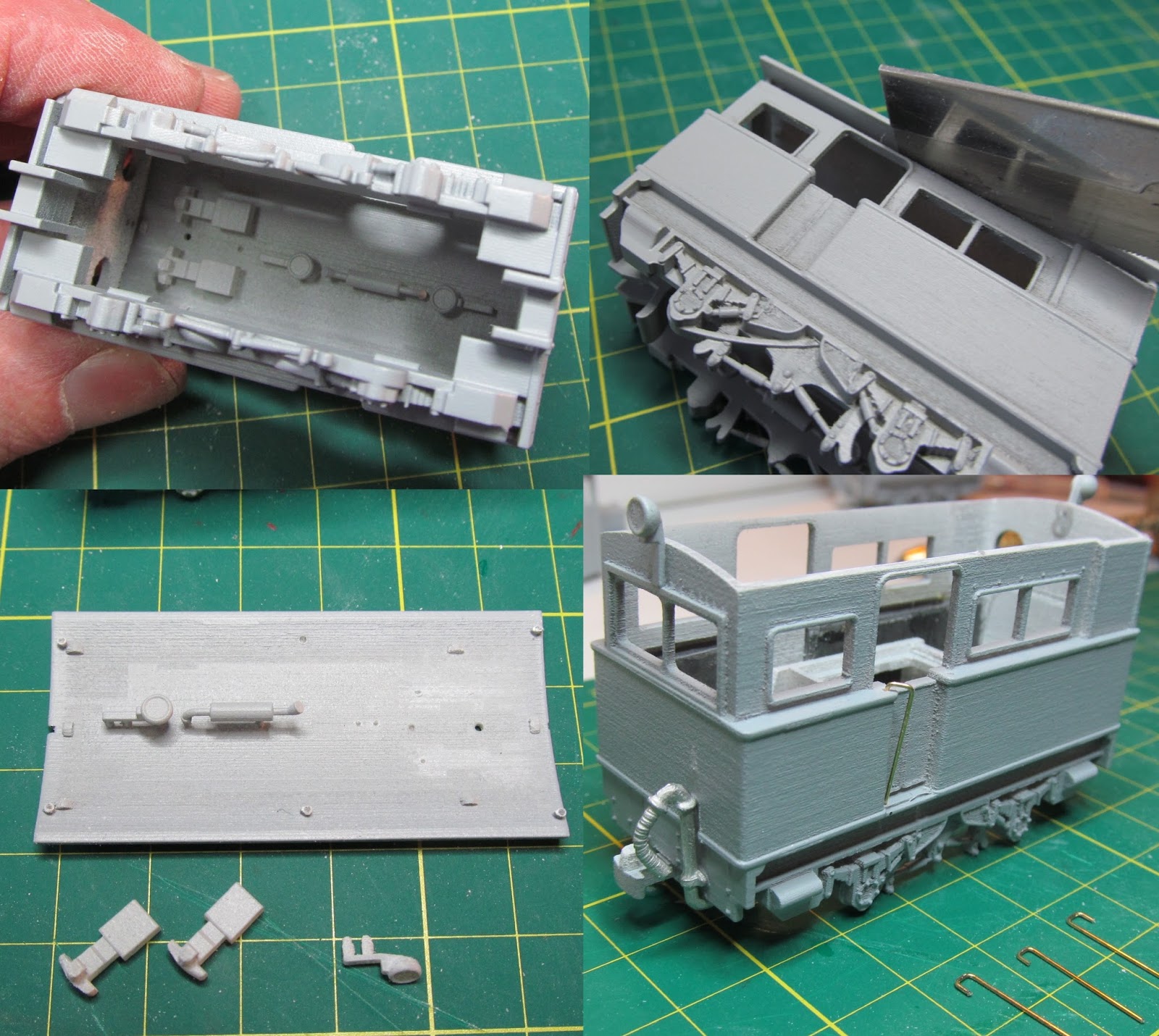
Ballast was
added to the coach body above the rear bogie in the form of two strips of lead
sheet bonded to the base of the interior with contact adhesive. The cab also
had ballast added to under the bonnet area and to the inner face of each side
of the cab or inside the cab behind the driver’s location.
Hugo Baart has very kindly sent a great picture of a different combination using a cab type C with a coach body type C, to come up with a more modern but short railcar combination. He has made some additions to the basic prints, like the grill, windscreen wipers, exhaust, luggage boxes, front and rear lights and interior lights. Also a soundecoder has been installed.
It will be fantastic addition to Hugo's layout "De Niggende Saligheyd".
It will be fantastic addition to Hugo's layout "De Niggende Saligheyd".
 |
| © 2022 Hugo Baart All Rights Reserved |
If you would
like a copy of this model it is available on Shapeways at Model Engine Works: