Sunday, 16 August 2020

009 Morris J Rail-Van


Built with Die Cast body and Kato chassis
009 Morris J Rail-Van
4 mm scale 

©  2020   David Hurst     All  Rights Reserved

 Hunting through the internet on my prolonged absences from work April 2020, I came across an Oxford Classix Morris J Van for sale on eBay, as this was for a very reasonable price and I had an idea for a small service van on a backwater railway, I bought it. 

©  2020   David Hurst     All  Rights Reserved

 Having received my van and dismantled it, I took a Kato 11-109 chassis and had a go fitting this into the body shell. The major alterations to the chassis had to be done to the front part of the unit, some metal had to be removed, this allowed it to sit in the right alignment to the wheel arches. To do this bit of cutting, I removed the plastic shell from the chassis and cut the front off using a cutting disk in a mini drill. One thing to observe when doing this the metal chassis is in two electricity isolated halves, so when the cutting is done make sure that there are no little bits of metalwork still bridging the gap between the two. This will cause a short circuit.

©  2020   David Hurst     All  Rights Reserved

 I then carefully removed just over half of the metalwork which held the plastic floor pan and wheels in place at each end of the inner body shell. This allowed the chassis to sit far enough into the body to place the centres of the wheels at the bottom line of the bodywork.

©  2020   David Hurst     All  Rights Reserved

 I then cut off the front and rear mudguards from the floor pan, which was a tricky job on the front ones as I did this by keeping the front part of the floor pan connecting them together, this made it much easier to line them up when fitted. These were glued to the metal bodywork with a little super glue, I did remove the paint from the wheel arches on the body first. The inside of the rear ones were made flush with the inner body, but the front ones I left to overhanging a bit and cut back the chassis to suit.

©  2020   David Hurst     All  Rights Reserved

The chassis needed trimming at both sides mainly at the front to squeeze into place. Once this was lined up I drilled a series of holes to suit 1 mm soft steel wire and formed some side rails and a front and rear bumper rail, and that was it, a relativity quick fix with no painting or finishing needed, though I will probably give it a coat of matt varnish and a bit of weathering. 

©  2020   David Hurst     All  Rights Reserved

The little van is a good weight because of the metal body and runs very well with the new style Kato chassis.

Saturday, 11 July 2020

009 Waddington Rail Bus


© 2020 David Hurst All Rights Reserved

It was quite by accident that I came upon a 1930s railbus photograph while searching for something else on the internet. I liked the 1930s aero styling and the design looked perfect to adapt to a narrow gauge variant. The original Waddington V8 railbus was designed as a feeder vehicle for the main railway lines in Sidney during the 1930s, running on standard gauge lines.

© 2020 David Hurst All Rights Reserved

The result of the drawing is a 3D printed version, which is printed as one piece to be split into the roof and upper body, and lower body. This can be printed in White Versatile Plastic or Fine Detailed Plastic with the addition of brass wire to form handrails. Couplings could be added to the model, but I have not added any to this version.


I had a sample printed by Shapeways in Fine Detailed Plastic. When this arrived I soaked it in Petroleum organic solvent – paint thinners (“White Spirits” in the UK) in order to remove the wax support residue left from printing. I then washed it in warm soapy water to leave the surface ready for painting when fully dried. I use a grey or white spray primer to prep the model for finishing. In some areas, it will be necessary to remove print lines from the surface, and this can be done with a burnishing tool - I use a hardwood stick with a rounded point to get in the tight spaces. Do these processes before separating the print into its component parts so you will be less likely to lose any of the small pieces.

© 2020 David Hurst All Rights Reserved

Wirework and details
The next job was to add the handrails to the door which is on the righthand side of the vehicle only. I obtained this from a supplier on eBay. The handrails were formed as small staples bent with pliers to the right size and fitted into the pilot holes supplied in the model. The handrails were fitted but not glued in place at this point in the construction process.

© 2020 David Hurst All Rights Reserved

The glazing was formed by making card templates of the windows and then transferring this to clear acetate, which I usually recycle from packaging. It is best to paint the model before adding the glazing material and gluing in place.

© 2020 David Hurst All Rights Reserved

The model has been designed to run on the new Kato 11-110 chassis, which are a welcome improvement on the later version of the 11-104 that they replace, having more weight, different gearing, a brass flywheel, and much smoother electric motor. They fit within a similar opening as the original. They do not need as much ballast to run well, but adding some is a good idea for traction. I used small strips of lead fitted along the inside of the bodywork, as low as possible to keep the models balanced right.
As mentioned, I did not use coupling on this version of the model, but if a small slot were made in the front bumper and above the rear bumper Greenwich or similar couplings could be used.

Painting and finishing
Once all the additional bits and details were added and before glazing the model, I gave the model a final coat of grey spray primer and made sure all was ready for the final paint finish. For this model, I used some Humbrol enamels. These were a mixed pale green and an off white. Some details such as the window frames 
and bumpers were picked out in a silver enamel paint. I applied a coat of matt enamel varnish to the whole surface of the model.

© 2020 David Hurst All Rights Reserved

The final job was to add the glazing in place to the inside of the upper bodywork. Once this was complete the bodywork was glued together and the handrails added and glued in place. 
I used Cyanoacrylate (super) glue to fix these components together.

© 2020 David Hurst All Rights Reserved

If you would like a 3D print of this model visit Shapeways at:

Wednesday, 10 June 2020

009 Fowler Style Tram engine


©  2020   David Hurst     All  Rights Reserved

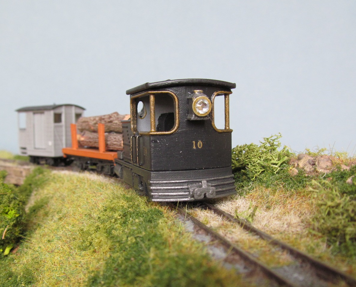
This is a “what might have been” Fowler style steam tram engine, based on a Fowler traction engine’s boiler and funnel, the cab of a steam wagon, assembled on a footplate to go on rails. The result is a reverse running engine cab first with a large forward facing lamp, but it looks equally well as a small engine with a high mounted boiler and oval cab windows running forward. It would probably be used in various industrial settings or on small roadside tramways around the latter part of the 1800s.

©  2020   David Hurst     All  Rights Reserved

I had a sample printed by Shapeways in Fine Detailed Plastic. When this arrived, I soaked it in Petroleum organic solvent – paint thinners (“White Sprits” in the UK) in order to remove the wax support residue left from printing, then I washed it in warm soapy water this should be left to fully dried before painting. I then used a grey spray primer to prep the model for finishing. In some areas, it may be necessary with some models to remove print lines from the surface, and this can be done with a burnishing tool - I use a hardwood stick with a rounded point to get in the tight spaces. Do these processes before separating the print into its component parts so you will be less likely to lose any of the small pieces.

Wirework and details

The next job was to add the handrails to the side of the cab. I obtained the wire for these from a supplier on eBay.  I formed the cab side handrails as small staples bent with pliers to the right size and fitted into the pilot holes supplied on the model. The handrails were then glued in place with Cyanoacrylate (super) glue.
The smokebox on the model is a simple top-hinged affair so no dart will be needed.
The new Kato 11-110 chassis are a welcome improvement on the later version of the 11-104 which they replace, having more weight, different gearing, a brass flywheel and much smoother electric motor. They fit within a similar opening as the original. They do not need as much ballast to run well, but adding some is a good idea for traction. I used small strips of lead fitted along the inside of the skirts, also on the sides of the water tanks keeping this as low as possible to keep the engine's centre of balance as low as possible.   

©  2020   David Hurst     All  Rights Reserved

The couplings I used on this model were from RT Models ref 4NLP005 white metal Penryhn Locomotive couplings. Others could be fitted such as Greenwich or NEM couplings. The aperture in the buffer beams will take the Peco 103 NEM pockets and couplings.

Painting and finishing

Once all the additional bits and details were added I gave the model a final coat of grey spray primer and made sure all was ready of the final paint finish. For this model I was trying some Tamiya acrylic paints, I had decided this was going to be an industrial-looking model and finished in black, so I used the XF-85 Rubber Black on everything except the front buffer beam, which I used XF-7 Flat Red. Using these I noticed that each colour has a different consistency, the XF-7 being thin and needing several coats were as the XF-85 was smoother, creamer, and needed fewer coats. I picked out some details like the window frames in a brass enamel paint and the cab handrails I left in the brass wire to match. The cylinders, couplings, lamp, and smokebox door were painted in a gunmetal metallic enamel paint.
I wanted to add numbers transfers to the model so I applied a coat of clear gloss enamel varnish to the areas these were to be placed. This is a better surface to apply the transfers to and allows you to adjust and position them much easier. I used “Fox” 2mm waterslide transfers in gold for the cab sides and rear only. Once this was completed, I applied a coat of matt enamel varnish to the whole surface of the model, this also seals the transfers in place.

©  2020   David Hurst     All  Rights Reserved

The final additions to the model were to add some real crushed coal to the two bunkers at the rear of the water tank next to the cab, by adding PVA glue to the bunker area and then tipping a small amount of the coal over this using a tube as a micro shovel to place it correctly. 

©  2020   David Hurst     All  Rights Reserved

In the past I have made some working lamps from white Plasticard and rhinestones of clear and red plastic and I used one of these for the rear running lamp for this engine and a larger rhinestone for the large lamp on the cab.

©  2020   David Hurst     All  Rights Reserved

©  2020   David Hurst     All  Rights Reserved

If you would like a 3D print of this model visit Shapeways at:

Thursday, 14 May 2020

Articulated Geared Engine

Revised 2020 to include funnel options

    ©  2020   David Hurst     All  Rights Reserved

The idea for this engine came from an original Hunslet catalogue. Although the design was, I believe originally produced by the Bristol-based Avonside Engine Co.  I was struck by the unusual format of the engine and the possibility of developing a design to run on a Bo-Bo chassis. I found that a good option for the chassis was the BANDAI B-Train Shorty Powered Motorized Chassis 3, which gave me the opportunity to design coupling rods and hubs to add to the wheels, as they did not have fixed axle boxes covering the wheelsets.


The bodywork and details
Note, in 2020 I added a straight funnel as well as the original with the spark arrester, to give a different feel to the model that you can build.  
The bodywork is printed in one main part with separate parts, which I think makes it easier to paint the model. The approach to finishing the print, which in this case is done in Fine Detailed Plastic, was to remove the wax support material from the print by soaking in petroleum paint thinners (white spirits in the UK) and then wash in warm (not hot) soapy water, leaving the model to dry overnight. I left all the parts attached together when I did this, so I did not lose any of the smaller parts.

©  2020   David Hurst     All  Rights Reserved

The first parts I removed from the bodywork was the frame printed directly under the footplate, which included the steam pipework, lamps, and couplings. This will expose the connecting rods and hubs. The cylinders are printed within the cab area and removed last.
At this stage, it is an advantage to spray the model in a grey primer which will hi-light any distortions to the surface caused in the printing process. I further separated the hubs and the cylinders from the main body now to allow me to clean the surface of the print removing any furring and surface lining caused in the printing process of the model. Once this is completed a further couple of coats of spray primer will give a good surface to work with.

The chassis adaption

The design of the coupling rods and hubs needed to be done so that the new hubs could be aligned and quartered to each set of the existing wheels. To achieve this I had the idea to print the rods and hubs as a set, which were at the correct centres and orientation to be glued directly to the wheels.

©  2020   David Hurst     All  Rights Reserved

The connection of the coupling rods to the new wheel hubs would be done using 14BA brass machine screws, nuts, and washers. These would be cut to remove the head and bonded into pre-printed pilot holes in the new extended wheel hubs, leaving them long so they can be trimmed off after final fitting.

The final print was set up with the four sets of hubs and coupling rods printed together off a central sprue. When fitting the hubs to the wheelsets, each pair of hubs still connected to a coupling rod has the 14BA threads put in place, which are glued in place and then glued to the wheel centres with a Cyanoacrylate (super) glue. A delicate job that needs to be done the right first time. Once this is done on all of the wheelsets the coupling rods can be separated from the hubs. The sprues will need to be cleaned off these and the holes in the coupling rods drilled out to give a loose fit to the 14BA threads. This loose fit is essential for the coupling rods to work without causing the whole mechanism to seize up. The washers are placed between the coupling rods and the nuts. These are not tightened but will be locked in place with a little contact adhesive when the final assembly is completed. You will find that all of the holes will need to be drilled out on both the hubs and the coupling rods. This is a restriction in the printing process the hole size can dictate the overall size of the printed parts.

©  2020   David Hurst     All  Rights Reserved

The other items to be fitted to each bogie are the coupling assemblies, which are fitted within the existing N gauge coupling pockets. These are printed as a frame and the rear part of this is pushed into the U shapes housing left when the N gauge couplings are removed. I used a contact adhesive to bond the print into the pockets. I found it easier to complete the painting of these before finally gluing them in place.

©  2020   David Hurst     All  Rights Reserved

There were a few bits to add to the model that I had sourced from suppliers. Smokebox door
darts were from RT models and the 0.45 mm brass wire I used for the cab handrails were from eBay. These were all added before the final coat of primer.

©  2020   David Hurst     All  Rights Reserved
Painting and lining

It is an advantage to fit all the body parts before painting and final fitting in place. The main body of the engine was painted in a Revell enamel paint, ref matt 56 blue. Several thinned coats were applied to achieve a smooth surface to the paint finish. Before applying the lining transfers to the model, a coat of gloss varnish was applied to the surfaces and left to dry. This gives a much better surface to apply the transfers to as it also allows them to be moved into place much easier.

©  2020   David Hurst     All  Rights Reserved

I also added a set of brass etched nameplates to the model, which were obtained from Narrow Planet who supply a large range of names and works plates are etched brass. They were fixed in place with a small amount of Cyanoacrylate (super) glue.
Other areas of the model such as the footplate, smokebox, funnel, couplings and bogie hubs were painted in a charcoal Revell enamel paint ref matt 9. In areas such as the steam pipes and cylinders, I wanted a metallic look to the finish so I mixed matt 9 with a silver 91 to get metallic gunmetal. I also hi-lighted some areas such as window frames and the dome with a brass finish paint. The buffer beams, hub faces, and coupling rods were finished in a Revell enamel paint ref matt 36 red.
Once all the painting was completed, a coat of matt varnish was applied over all areas, which has the effect of sealing the transfers and smoothing the joint between the etched plate and the model. If any area needed a gloss or shiny finish like the dome, I applied a little more gloss varnish to them. 

I sorted out some figures for the crew and adjusted them to fit within the cab. It turned out better to add these to a small base plate and then paint them and was also much easier to add them into the cab afterwards.

©  2020   David Hurst     All  Rights Reserved

The final touches to complete the model was the add some real coal into the bunker at the rear using PVA adhesive and real crushed up coal. Then the lamps were given some sparkle with some clear plastic rhinestones of a suitable size.  

If you would like a 3D print of this model visit Shapeways at:


Sunday, 10 March 2019

009 Skylark Style Engine


3D print of this engine is now available at Model Engine Works on Shapeways.


©  2019   David Hurst     All  Rights Reserved

One small engine which a lot of people seem to have on their layouts is the Kerr Stuart 0-4-2 Skylark. Most use the white metal kit and a chassis such as the Ndrive 0-4-0 with a pony wheel added. I was impressed by the one built by Michael Campbell using the Kato chassis with side plates which mimicked the pony wheel with the rear wheel of the Kato chassis, a simple but really good solution. http://michaelsrailways.blogspot.co.uk/2012/10/a-little-bit-of-skirt.html

©  2019   David Hurst     All  Rights Reserved

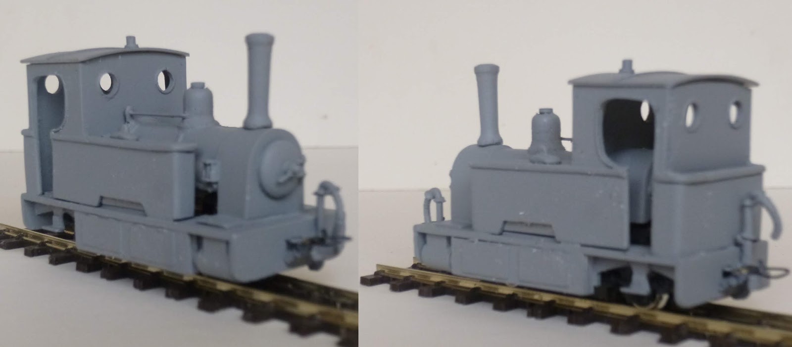
I decided to have a go at scratch building my own version of the Skylark. As I was looking to build something in this style rather than recreating the actual engine, there were possibilities to make a few changes to the model and still keep the look and spirit of that style of engine.
I got as many reference pictures as I could find together and also one of the Kato 11-104 chassis. 

©  2019   David Hurst     All  Rights Reserved

These are very good when getting into modelling 009 narrow gauge engines as they are so reliable and inexpensive. These can be used on engines that are made with side plates, which were usual on roadside tramways built in the UK and Ireland.
I started by making a mock-up footplate, to get the right-sized opening to fit the chassis. Once I had that sorted I made a few scale drawings of the bodywork, using the pictures as guidance.

©  2019   David Hurst     All  Rights Reserved

My plan was to build the engine from different thickness of sheet Plasticard and spare pieces from old model kits that had been left over. 
To make the body I printed some paper patterns from the drawings that I had made, which were temporally fixed to various thickness of Plasticard with Pritt stick. This holds them long enough to cut out and the paper then just peels off afterwards.
The smoke box having a round top was formed using 1mm front and back shaped pieces fixed to the rectangular base. Then thin sheet Plasticard was formed over this in two layers. This is easy to bend to shape and by gluing the additional layer strengthens it up. The same idea was used on the boiler, with an additional layer being used to create the bands around the boiler. Of course if you have the right size tube this will save going to the trouble of making the boiler.
The chimney and dome were made using lime wood and turned in the chuck of a small electric drill.

©  2019   David Hurst     All  Rights Reserved


If I had known about the “Gem 9104” white metal OO-9/ industrial loco fittings beforehand I would have used one of these chimneys and the dome.

The smoke box door was made up of two discs of 1 mm Plasticard sanded to shape, the hinges and handles were added using spare bits from an Airfix 040 saddle tank kit.I formed the spectacle windows by drilling an oversized hole and lining this with strips of thin Plasticard sheet to give the impression of a brass frame when painted. I made use of a pair of vacuum pipes from a spare Vale of Rheidol coach.  
 
©  2019   David Hurst     All  Rights Reserved


The upper edges to the water tanks have a strip of the Plasticard added round the top  and this is then filed to a D shape with the top inner edge softened, which forms a slight well at the top of the two side tanks.
I used one of the Dapol track side figures for the crew. I did find that I had to shorten the legs on this figure as in general they are slightly over size in some of the smaller engines.  

©  2019   David Hurst     All  Rights Reserved

I made the lamps in bulk some time ago using white 1 mm thick plasticard rectangles to form a 3 x 2 x 2mm block and then added a 2mm disk on top, and for the lenses I used a small 2mm clear or red rhinestone. 
The paint was a mixture of various Humbrol colours to produce a shade of maroon that I liked. A final coat of matt was added to the footplate and smoke box, then satin varnish over the maroon painted areas. I used real crushed coal in the bunker – you need to get this almost like dust at this scale to look right.

©  2019   David Hurst     All  Rights Reserved

The finishing touch was a set of name and works plates from Narrow Planet who do the brass etched plates to order. “Fergus” was my chosen name with a separate set of works plates.

©  2019   David Hurst     All  Rights Reserved

 It has been a good practice run for me and I have enjoyed the challenge of the build.


This popular little engine is now available as a 3D print to run on the readily available Kato 11-104 chassis. It has separate foot plate body and roof to allow for interior details to be added, there are also a pair of simple couplings printed under the foot plate of the model.
Additional details will be needed to complete the model as show, these include smoke box door handles, cab side handrails and working lamps.

©  2019   David Hurst     All  Rights Reserved

If you would like a 3D print of this model visit Shapeways at:


Friday, 16 November 2018

009 Tattoo Class 0 4 2

 A venture into white metal kit building.
©  2018   David Hurst     All  Rights Reserved

The Kerr Stuart “Tattoo Class” is a favourite of mine and I have built quite a few models based around this type of engine. They were built by Kerr Stuart & Co in large numbers at the beginning of the 1900’s as a small workhorse engine, the majority being for 2 ft gauge lines and having outside frames, to accommodate the firebox. There were however quite a few built for wider gauges 2ft 6” and 3ft with inside frames. Being a basic engine, most had open cabs, though some had enclosed cabs added in different forms at the time of manufacture, or later by their owners. 

©  2018   David Hurst     All  Rights Reserved

A Christmas gift I once received was a white metal version of the Talyllyn Railway’s engine Edward Thomas. I had also had an Ndrive Productions 0 4 0 Chassis which was a suitable size to fit the kit, needing only the addition of a rear pony wheel. The spark that prompted me to finally build the model was a holiday in mid Wales, where I planned to visit the Talyllyn Railway and perhaps see Edward Thomas in person. 

©  2018   David Hurst     All  Rights Reserved

I started by looking for the right candidate for a pony wheel, which needed to be around 5.3 mm. There was also the question of how to mount the wheel onto the chassis. Now Ndrive Productions (Neville) has a nifty little etched universal mount to do this job, a cross with several holes to fit the wheels and create a pivot. The only thing was that you needed a wheel set that separates from the axles (to pass through the holes in the pony truck etch). 
 
                                                         ©  2018   David Hurst     All  Rights Reserved
I discovered that the Kato wheel sets are held together with a plastic tube (to electrically insulate the wheels) and are close to the right size for the pony wheel. By filing off the pinpoint bearing and carefully opening out the hole in the etch I had a basic pony wheel and mount. Having selected the suitable pivot hole on the etch, it was then a fiddly job to drill a small very accurate hole to take a 10 BA cheese head machine screw in the base of the chassis. Care is needed as you are working very close to the gears, (so don’t slip)?

This pony wheel assembly is very light and does not ride on the track well in reverse, although its wheels are free moving and it pivots easily. The etch being a cross shaped form does give the opportunity to add a little weight at the back of the wheels. The 10 BA cheese head needed to be filed down to a thin disk with a new slot cut across it, to avoid catching on the track at points. It was also necessary to file down the wheel pick-ups at the back of the chassis or the etch for the pony wheel would not pass over these.
The other areas of the chassis that needed to be fettled were above and in front the cylinders. These needed to be filed off and cut to allow the chassis to sit tightly up to the underside of the footplate. Also, the width of the rear bar needed reducing at both sides.

©  2018   David Hurst     All  Rights Reserved

To say that this kit was designed for another type of chassis, it was a surprisingly good fit. There was a small area for the cab front and underside of the boiler to remove to accommodate the slightly bigger motor, a few tweaks to the footplate at the front a small square to cut out for the worm gear, and that was it. The body and the chassis were held together by forming a small L shaped bracket at the back and glueing this to the underside of the cab, this formed a channel for the rear of the chassis to hook into.

©  2018   David Hurst     All  Rights Reserved

The front fixing of the bodywork uses the existing counter-sunk machine screw and nut supplied with the chassis. This was done by slightly deepening the counter sink in the chassis and glueing the nut to the top face of the footplate situated above the existing hole. All of this was done before the bulk of the model was put together. I also added the blast under the saddle tank and in the smoke box before final assembly. It needed more weight at the front to counter the overhang of the cab, and partly to reduce this weight. I did not use the cab roof since this appeared too thick and bulky ,but instead formed one in Plasticard sheet, creating the gutters which the metal roof lacked.
Other modifications to the model included adding brass 0.45 mm wire handrails to the cab sides and above the smoke box. Also water feed pipe work under the saddle tank was added to hide the cogs and worm gear.  The shape of the cylinders was changed by using some Plasticard sheet to make them look more like the prototype. The buffers were not used on this model, only the supplied coupling plus some lamps and tool boxes.

©  2018   David Hurst     All  Rights Reserved

Paintwork on this model was completed when it was fully assembled, apart from the cab roof which was left loose to allow the cab interior to be finished. To prime the metal and plastic structure I used a matt grey spray primer suitable for metal and plastic surfaces. The finishing paints where oil-based enamels. The green used was a mix of deep Brunswick green and light grey green. The black areas were a mix of matt black on the smoke box and funnel, the other areas being painted in a charcoal grey. I used a signal red on the buffer beams, whilst inside the cab was left in the grey primer finish. Small details such as pipework and safety valves were picked out in a brass metallic finish. The whole model was finished in either a matt varnish or satin clear varnish once details such as the works plates and name plates were fitted.

©  2018   David Hurst     All  Rights Reserved

The set of etched brass plates were supplied by Narrow Planet, who produce a set specifically for “Edward Thomas” from the Talyllyn Railway.     

©  2018   David Hurst     All  Rights Reserved

The engine crew was an adapted Dapol Line side work crew figure , with one leg shortened to suit the height of the footplate whilst still looking like a 4 mm scale figure.