Wednesday, 10 December 2025

Wiring directional lighting into a Kato 11-110 Chassis


© David Hurst 2025 All Rights Reserved.
I took a closer look at how the Kato ‘Hayau-Go’ rocket train’s LED lighting has been fitted - it is a fantastic little bit of fantasy and has the interesting feature of directional LEDs. Kato have used a split chassis design which makes it easy to pick up power. There is, however, an interesting property with LEDs: they are polarised, and only work if wired to the correct polarity. This got me thinking that a model can have lights which work only in the direction of travel – a simple case of switching the wiring polarity to work with the direction of travel.

© David Hurst 2025 All Rights Reserved.


I decided to try this as a practical experiment and used an idea that I saw at the 009 Rainhill and AGM meeting in April 2025: a small rail van with working lights. I planned to use an old Hornby diecast Austin van. These were sold by Hornby sometime ago as white primed vehicles that you can dismantle and paint yourself and were ideal for what I had planned.
I removed the glazing, plastic interior and wheels, leaving the metal body work, from which I cut off the spine used to screw the interior. The other modifications were to drill a hole in the roof for a 3mm orange flashing LED - this will illuminate in forward travel. I also cut of the bodywork forward and behind the wheel arches - this removed 2mm of metal which I filed flat. This allowed me to sit the body on to a 3D printed foot plate into which a Kato 11-110 could be fitted.

© David Hurst 2025 All Rights Reserved.

I intended to use the current head lamp holes for a white and red LEDs which will illuminate depending on the direction of travel. As these holes were smaller than the 3mm LEDs, I opened them out on the inside so the LEDs would be closer to the surface just showing through. This allowed me to paint a thin wash of black over them to reduce the intensity of the light to a glow.


© David Hurst 2025 All Rights Reserved.
I now turned to the power pickups from the Kato chassis. The easiest way I could see of doing this was to piggyback the current motor pickups; but I wanted to make the setup serviceable. To make this work I used bronze strips with black and red wires soldered to them and slid these into the pockets where the current pickups are housed. This needed a little adjustment to the pockets to allow for this, but worked well. The bronze strips were then cut and bent to feed the wires out through the plastic top on the chassis. Once the top had two holes drilled and then clipped back onto the chassis it all held in place nicely and did not affect the running qualities of the unit.

© David Hurst 2025 All Rights Reserved.

The next step was to test the theory behind the idea. I used pre-wired LEDs from Bright Components on eBay, which I find very good for this kind of project. I used a small 5-amp connector block to attach the wires to the pickup tails from the chassis and did a test run on some track to see if this would work as intended - which it did. In forward motion the white and orange flashing lights worked, and in reverse the red one worked, so that was all good. 

© David Hurst 2025 All Rights Reserved.
To mount the Kato chassis in the correct position on the body work I drew up a simple footplate with cow catchers at the front and a NEM coupling pocket at the rear. After a couple of prototypes this fitted and allowed the chassis to sit nicely into the body. To get the wiring to fit I had to take some of the plastic shielding off the connector block and make it into two separate parts. I decided that I would paint the body before assembly and went for a deep red and cream livery with a grey roof. I did yellow panels to the front and back which does give a more modern vibe; to tone this all down I applied some matt varnish, and, when this had dried, a black acrylic wash to pick up door panels and shading.

© David Hurst 2025 All Rights Reserved.
The lighting was fixed in place on the body with a hot glue gun. Then the footplate was added to the metal body, bonded with super glue. The wiring could now be connected to the chassis, and all squeezed into place within the body - this was a tight fit. I disguised the wiring with black insulation tape so that it could not be seen through the windows. This was also used to stop the light from the LEDs shining into the cab. With everything squeezed together I sat it on the track and crossed my fingers. It worked, even at lower speeds the lights were still visible. To finished off the model I added some wire guard rails between the wheels which I painted yellow and chipped some paint off when dry to create a used look. The NEM coupling pocket came in useful - it allowed me to add a flat wagon or van behind for tools and materials. With the van being metal it has good weight and has some pulling ability.


© David Hurst 2025 All Rights Reserved.


© David Hurst 2025 All Rights Reserved.

Sunday, 22 June 2025

009 Victorian Single

 2025 David Hurst All Rights Reserved

When I heard that Bachmann had produced an Emily in their N gauge Thomas range, I could not wait to get hold of one. I have always loved the Dean single that Hornby has produced for years - I had one in my early teens. My thoughts were to design a fictional 009 version, a cross between the Dean and the Sterling singles that Emily is based on, keeping that elegant Victorian look.

© 2025 David Hurst All Rights Reserved

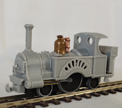
When my Emily model arrived, I wasted little time before it was dismantled and inspected to see how I could achieve my goal. The main chassis comprises the large central driving wheel and a smaller one in front, geared to work together. The rear wheel is non-driving with a lot of free play to allow for curved track, while the front wheel set is on a bogie incorporating the NEM coupling pocket. This allowed me to look at two arrangements: a 2-2-2 tank/tender and a 4-2-2 tender loco. Both using similar body work, just a different front foot plate.

© 2025 David Hurst All Rights Reserved
I could see the difficult part of this conversation would be the smoke box, cylinders and piston slides, which are very small and incorporated in one moulded assembly. I could have used the existing one but that would limit the design. So, my first job as always is to get the chassis into a CAD format, then I can work round it and develop the body work. I could see that the new bodywork would need to follow the same assembly process as the original Emily and use the same fixing points and screws.

 2025 David Hurst All Rights Reserved

The first part to tackle was the smoke box and cylinders. I worked on this to achieve a good fit to the chassis first, developing the shape to match the existing Bachmann parts, then I designed an outer shape to get the feel I was looking for in 009 scale - something very similar to the Sterling, a nice flowing shape between the cylinders and smoke box. The difficulty with this part was adding the wire guides for the cross heads in 0.4 mm wire on either side of a 0.7mm hole for the piston rod. After several attempts at printing these, the best solution was to have a pilot hole for the piston only printed in the part and free hand drill the holes for the guides above and below the piston. It is still a fiddly job, and I wasted several printed parts getting it right. This was confirmed by A fellow 009 modeller, who has also worked on another copy of the model and found it difficult to drill the holes to fit these wires in place. The other option is to use the current Emily smoke box and extend the funnel. However, this does not align with the new boiler profile.

© 2025 David Hurst All Rights Reserved

The coupling rods need removing from the large driving wheels to make it easier to locate and fit the cross heads to the guides. A very small bolt is used to fasten the rods to the centre of the driving wheels which is a fiddly job to put back in place.


When I had the smoke box fitted to the chassis and the piston working freely, I then tested the chassis running it on a test track. The next task was to deal with its main body design. This is where I planned to blend the Sterling and the Dean together. My aim was to have the fretwork showing the large wheels like on the Stirling, with water tanks to the front and back of this, on the 2-2-2 tank engine. The tender loco would have large curved shrouds built up to the rear of the splashers back to the cab front, with the top of the boiler and the cab being similar to the Dean with the brass dome and curved cab side cutouts. The back of the cap would remain open, and I would add some simple printed details to the interior, with other fine detailing added in metal parts. I used an etched fret from RT Models to do this, which has various gauges and valve handles. The regulation was made from 0.7mm wire filled to shape.

To get the tank engine version of the model to work I needed to add a coal bunker to the rear foot plate somehow. As the cab was coming out a bit higher than I wanted, I lowered the back of the foot plate by 1.5 mm. By dropping the cab down the same amount, I then could use this to add a plate on top of the cab floor, like a step within the cab but as part of the bunker assembly. The bunker itself was modelled on an older pannier tank engine - the open cab type. This has a nice shape matching the Dean styling of the cab and can easily be added to the cab to form a very different version of the engine.

© 2025 David Hurst All Rights Reserved
                            
The front foot plate has two versions: one suits the chassis without the front bogie wheel, being short and having a coupling pocket below the front beam. It is all printed as one with the front of the smoke box.
© 2025 David Hurst All Rights Reserved

The other is longer and uses the current n gauge NEM coupling pocket in the bogie, which is ideal to add 009 style couplings.

© 2025 David Hurst All Rights Reserved
I have made several detail parts separately to allow some variations to be added to each model. The funnel can be cut to different lengths. The dome is printed, but I used a nice cast brass one again from RT Models. The water tank filler caps are printed, but again white metal one could be used. There is a separate smoke box door with a pilot hole for darts to be added. This was another part from RT Models. I have also printed a reversing leaver to add inside the cab.

© 2025 David Hurst All Rights Reserved
The tender I have used is an adaptation of a general 009 one that has been designed for some of my other models. It is a 4-wheeler using a Peko R106 wagon bogie with a 3D printed body and foot plate. The design of the upper body has been adapted to align with the new engine style and a simple drawer bar and pin is used to connect it with the locomotive - like the current Emily one, but this time in Plastcard. I printed a break handle column to which I added a handle using a small handrail knob and a handle bent from 0.45mm wire. To fall in line with the Victorian tender style I added a wire guard rail around the sides and the back of the upper edge of the body work made from very fine 0.45mm brass wire bent and super glued into place.

© 2025 David Hurst All Rights Reserved

For the colour scheme of this model, I want to match my current 009 Beyer Peacock in the older GWR livery for the tender loco and a mustard for the tank engine. I found some Vallejo acrylic paints in green and red that meant I would not need to mix the colours this time giving a more consistent finish. So, having fitted the brass components, I primed the model in a combination of Tool Station rattle can acrylic grey primer and clear gloss lacquer, built up in alternate coats to smooth the surface before the final hand brushed finishes which are thinned with Vallejo acrylic thinner medium. This allows a better flow off the brush and dries slower allowing it to level and not show brush marks.

Once I had applied a few coats, I added 0.35mm cream lining by Fox Transfers to form panels on the tender and cab and banding on the boiler. I also hand-painted the large wheel splashers in a matching cream.

To allow me to at least display the other version of the model as the chassis is not cheap, I used the chassis drawings to create a print of both the 4-2-2 and 2-2-2T as dummy chassis.

© 2025 David Hurst All Rights Reserved
I asked a fellow 009 modeller to have a go at building a model to see if they encountered any issues. They concluded that drilling the two fine holes for the guide wires was their main difficulty, but it may be easier to achieve on a drill stand.
© 2025 Hugh Norwood All Rights Reserved
It is extraordinary to think that someone may have built something like these singles in narrow gauge, but a fellow 009 modeller on Facebook noted that three narrow-gauge singles were commissioned for the Glasgow Garden Festival 1988. They were built by Severn Lamb Ltd based on the Caledonian Railway 4-2-2 Locomotive no 23, and were diesel driven by the tender. Apparently, at least one of them has been sent to Japan and used in the Rusutsu Resort there.


© 2025 Open image All Rights Reserved


Tuesday, 31 December 2024

00n3 & TT:120 Chassis Conversion

Kato 11-110 Tram Chassis Conversion to 12mm Gauge


It's been a long-term goal of mine to find a readily available economical chassis for 12mm gauge use. This would give 00n3 narrow gauge modellers an equivalent to the Kato tram chassis that 009 modellers have, allowing entry-level tram engines to be accessible at a reasonable price. As a side note, this may also suit modellers of the TT:120 scale.

After working on various alternatives for some time, I finally asked myself: could I convert the Kato chassis and regauge it? So that's what I did ― and it's simple to do, using the new 11-110 version with the cordless motor. The only new bits needed are some small spacers to reset the gauge of the wheels. The rest of the work involves modifying what you have with the existing chassis.

The best way to explain this is with pictures and notes, so I have attempted to do this in the following instructions:


1 Remove the couplings from each end of the upper shell. They are clipped in place, so pull off quite easily.

© David Hurst 2024 All Rights Reserved.


2 Remove the balconies from each end of the upper shell. I cut these off with a pair of Xuron Track Cutters ― they cut the plastic cleanly and do a neat job.


© David Hurst 2024 All Rights Reserved.


3 The next step is to remove the four axel boxes from the upper shell. There are two cuts on each one: first a small nick at the inner end, then cut straight across the top. Then clean the cuts off with a craft knife.


This is important as the upper shell needs to be clear of the pickups.


© David Hurst 2024 All Rights Reserved.


4 The lower shell needs to be trimmed to allow clearance for the bends on the pickups. This requires two cuts in each corner ― it may be easier to cut these with a kraft knife. There is also a bit to trim off each of the end tabs (the small lip that sticks up).


© David Hurst 2024 All Rights Reserved.


5 Take the metal pickups and using a pair of fine pliers bend these at each end to form a very slight Z. The idea is to induce a 1.4mm offset to work with the wider wheelsets.


© David Hurst 2024 All Rights Reserved.

I have noted that this can be difficult to get consistent, and I have developed a press to achieve this.


The following shows the method to use the press:

© David Hurst 2024 All Rights Reserved.

It has a core into which the pickups are inserted with the outside facing the arrow. It will centralize when pushed right down into the slot. Fold up the sides, and press these together to form the bends in the pickup. The metal is soft and bends easily.

I can supply a press on request at modelengineworks@outlook.com

6 Next take the wheel and pull the metal parts away from the central plastic tube and gear. They are only a very good push fit so will not take a lot of force to remove.


© David Hurst 2024 All Rights Reserved.


7 The next step is to add small packing disks that are 1.4mm thick to the metal wheel pins. This will leave just enough of the pin to push back into the original tube. These can be made from a Plasticard sheet using a hole punch to make the 4mm diameter disk, then drilled with a 1mm central hole so it is a push fit to the axel. I made some on a 3D printer, and can also supply these on request at modelengineworks@outlook.com. The results are similar using both methods.


© David Hurst 2024 All Rights Reserved.


8 Return the wheel sets to the chassis ― they are not handed so they fit at either end.


© David Hurst 2024 All Rights Reserved.


9 This is the start of the fiddly jobs. The pickups are returned to the chassis: these need to be kept in their correct position while the bottom shell is clipped on.

© David Hurst 2024 All Rights Reserved.


10 It is important to get the bottom shell correctly orientated to the metal chassis. There are arrows on the shells that point to the front of the position where the worm gear is located.


© David Hurst 2024 All Rights Reserved.


11 Before replacing the top shell: as the motor is loose at this point, the red pad on which it sits can become dislodged, so make sure it is correctly positioned in the metal chassis. At this stage to keep the motor in place, I added a small strip of black insulation tape around the hole unit to keep things in place and to test if the chassis runs OK.

© David Hurst 2024 All Rights Reserved.


12 After testing, the top shell can be returned to the chassis. Look out for the orientation arrow, and then clip this in place.


© David Hurst 2024 All Rights Reserved.


13 Now test if the chassis runs. If there is a problem: I have found that the areas above the pickups where they are bent out may need more clearance ― they need a bit of free play up and down. The other area that can cause issues is the pickups being too tight on the wheel: these are best with a little free play or less pressure on the wheels and may need to be eased out from the wheels.


© David Hurst 2024 All Rights Reserved.


The conversion has now been carried out successfully by several other 00n3 modelers.

They have found that the pickup is a difficult part to bend by hand. Also, these must have the correct clearance above the wheels to allow movement. It is also important to get the bottom plastic cover on the right way round, or this will cause the gears to bind with it, or not clip in place.

See the conversion by Paul Titmuss running on his 00n3 layout 'Lispole' on YouTube.


A copy of the press and spacers can be supplied on request at modelengineworks@outlook.com


Sunday, 14 April 2024

009 Tram Shelter

 2024 David Hurst All Rights Reserved

On the bus route to work from Huddersfield to Elland, I kept noticing a very unusual bus shelter. It stuck in my mind because it looked so ornate and out of place. On one of my journeys in 2020 I walked to the bus stop just to have a closer look and I was not disappointed. It is a fantastic little building, built of wood and painted in cream and red with a grey slate roof and lots of little details. Before my bus came I did a quick measure and took lots of photos. It was a much more interesting wait for a bus than normal that day.

 2024 David Hurst All Rights Reserved

I did a little research into the history of the building. It was built by the Huddersfield Corporation Tramways in 1896, which was the first local-authority-run tramway service in England and was built to the unusual gauge of 4 ft 7 3⁄4 in to attract traffic from neighbouring coal tramways. The shelter was presumably repurposed in 1934, upon the conversion of the Linley and Outlane line to trolleybus. The entire Huddersfield network was converted over the 1930s (the tram network officially closed on Saturday 29th June 1940), and was itself replaced - and the shelter once again repurposed - when the trolleybus network was superseded by buses in 1968. Unfortunately, as with most of our very nice Victorian infrastructure, the shelter became unnoticed, unfashionable, and neglected, despite being Grade II listed in 1977. Its fortunes changed in recent times: in 2015, the West Yorkshire Passenger Transport Executive applied to restore the shelter to its former condition and H.C.T. colours of vermilion and cream. This is why I had noticed it. I have since found out that the shelter once had a central coal stove and the roof apex once had a chimney, not the finial that nicely finishes off the restored roof.


Fast forward to December 2023. I had just got a new 3D filament printer and was looking for something interesting to challenge both the machine and my drawing skills when I remembered the shelter. It had a good level of detail and an interesting shape. So off I went and disappeared for several hours doing the drawing. I then had the new dark art of “slicing” software to navigate before unleashing it on the printer.

The results surprised me. They were good, not perfect, but a good basis to work with to create a model with a level of detail at a 4mm scale. I wondered if I could go smaller so tried a 3 mm scale and then 2.53mm TT120. They both worked but with some of the finer window details removed as the printer's 0.4 mm nozzle and 0.1mm layer thickness was just not fine enough. Also at the two smaller scales, the details are just not that visible.

2024 David Hurst All Rights Reserved

The 4mm scale version I did in three sections: the roof, walls, and floor. It worked well for printing and allowed the interior to be accessed for painting. For the smaller scales, I just did the roof and walls, though I am sure a floor will print with the floorboard details.

© 2024 David Hurst All Rights Reserved

There was a little bit of cleaning up to do around the windows, and also the underside of any overhangs are challenging to get smooth on the printer. I have found that small needle files are a very good tool to smooth things out in these areas. Printing on a fine setting does give a good finish to the model and although there are areas with some fine lines these are not difficult to overcome. When preparing the model for painting I used a spray matt primer in either white or grey then gloss spray lacquer, which has the effect of levelling the surface. I applied two or three coats of each and this gave me a smooth surface to paint on.

Painting the first model I used Vallejo acrylic paints, each thinned with a little thinner medium and applied in multiple thin coats and washes to highlight shading. I decided to try and go with the current colours of the shelter and used a mix of 70.926 Red and 70.947 Dark Vermillion on the lower panelling and details, 70.837 Sand on the windows and upper details, 70.826 Black Grey on the roof and floor concrete base. This was mixed with 70.951 White to create a light grey for the concrete base and a mid-grey for the roof tiles. It was also used to dry brush over the roof area. The floor was based out with a light grey and then a black wash to get between the boards and finally dry brushed with the sand. For any areas with lead flashing, I mixed a bit of the black grey with some 70.997 silver to give it a metallic grey look.

© 2024 David Hurst All Rights Reserved

It has been an enjoyable venture into the world of home printing my own models and learning a new skill, and though it is not to be compared with commercial printing such as Shapeways, it has a place for those of us who like the challenge of trying something ourselves. I picked a filament printer as it uses less messy materials and takes up less work space than resin printing, so would do for me at this time. Things are changing fast though, so that will change I am sure.

© 2024 David Hurst All Rights Reserved

Based on the original panels which I have drawn in a modular fashion, there are some variants of the original shelter also - these include a hexagon smaller version a double-fronted rectangular type and two-handed smaller rectangular versions. 


If you like the model and would like your own copy please get in touch with me at modelengineworks@outlook.com and I will do my best to help.


Sunday, 6 November 2022

009 Chiemsee-Bahn Style Steam Tram

© 2022 David Hurst All Rights Reserved

Following on the theme of the steam trams I had a look at European types and found some really good candidates to suit the new Kato-Peco Small England chassis, one stood out for me, the meter gauge Chiemsee-Bahn tram looked a perfect match for the chassis.

© 2022 David Hurst All Rights Reserved


The Chiemsee-Bahn (Chiemsee Railway) is a meter gauge line in Prien am Chiemsee, Germany. It is one of the world's last steam tramways and is said to be the oldest continuously operated steam tramway in regular operation.

It has worked out as a very compact model, and as such, I have ended up adding the couplings to the buffer plates and not using the Peco coupling pockets which I would normally use. It is a superb running model and I think my favorite tram from my ever-growing collection.


© 2022 David Hurst All Rights Reserved

To allow for fitting details inside the very small space in the cab that is left after accommodating the chassis and the large weight. I have made the whole of the upper cab including the roof and supports separate from the lower body. This has allowed me to fit a figure with its lower half removed. I used one of the Dapol trackside work crew. It also makes it possible to add pipework and controls if you like.

© 2022 David Hurst All Rights Reserved

There is a bit of deviation from the original tram around the smoke box door, this was purely for the structural stability of the roof supports and to locate the upper and lower sections. The smoke box door is printed as a separate part, I used a dart from RT models.

© 2022 David Hurst All Rights Reserved

The handrails have small pilot holes formed to give a guide for drilling out to suit the wire used. My choice was 0.45mm brass. There are three small lamps added with the print, two for the front of the tram and one for the rear, I added some clear and red rhinestones to form the lenses on these. There are holes in the front of the bodywork for the lamps, but you can decide if you want to fit the rear one and where to position it.

© 2022 David Hurst All Rights Reserved

One of my modifications on the prototype was to abandon the NEM pockets and to fit a set of RT models Penryhn Locomotive couplings, as space is a premium inside the lower bodywork. I have added a similar printed pair to the model on Shapeways now also some location holes on the buffer beams.

© 2022 David Hurst All Rights Reserved

Finishing the model was done in oil-based enamels, the black was Revell M09 Anthracite and the green was a mix, not as bright as the original. The roof was left in the grey primer. The lining used is Fox Transfers cream 0.35mm, and this is sealed with a matt varnish.

© 2022 David Hurst All Rights Reserved

It goes well with a small tram coach which I converted from an Atlas tram model obtained on eBay.This started out as a Berlin tram in a 1:86 scale which I added a 4mm section between the footplate and the bodywork to raise its height and give it the height to look like a 4mm scale model. Under the footplate I used a Peco wagon frame split in half to extend the wheelbase and some etched brass mesh to form side guards to the chassis. The foot plate being of metal gives it enough weight. Because of using the Peco wagon frame, I was able to fix Peco NEM pockets and couplings directly under the footplate. With the paintwork being superb on the Atlas models I decided to keep it untouched, the additional section that I added was painted in a contrasting darker green and the footplate was lined in red.

© 2022 David Hurst All Rights Reserved

I have made this model available on Shapeways if you would like a copy of the print. see the link below.

009 Chiemsee-Bahn Steam Tram (649WKSZ4H) by tdhurst (shapeways.com)